While I'm waiting for some molex pins to arrive so I can finish the Left Elevator, I started some work on the AFT Fuselage. This is the last piece of the Empennage Kit. When this piece is complete, all the pieces of the empennage kit (vertical stab, rudder, horizontal stab, elevator, and aft fuselage)will be joined together and tested for proper fit. Then it's time to start the wings!
The first couple of pages of the Aft Fuselage plans involve some basic fabrication of a few parts that will be used later. Mostly just separation and trimming using a band saw and metal cutting shears. Well....towards the end of a productive day, I got a little sloppy with the band saw on one piece and made a mistake. See pictures below. I'll be ordering a replacement on Monday.
I spent a few hours today fabricating the left and right rudder stops from the pre-drilled angle supplied with the kit. I was extra careful with the band saw this time to avoid a mistake like I made with the HS Attach Bar seen above (still waiting on that replacement part).
I received the replacement for the Horizontal Stab Attach Support that I messed up on the band saw earlier. Turn out much better the second time.
When starting a new section, the normal flow seems to always include some trimming of parts, match/final drilling and, of course, the ever popular de-burring. This is holding true for the Aft Fuselage. Some of the first match drilling in this section involves the Aft Fuselage Bulkheads and the previously completed Vertical Stabilizer.
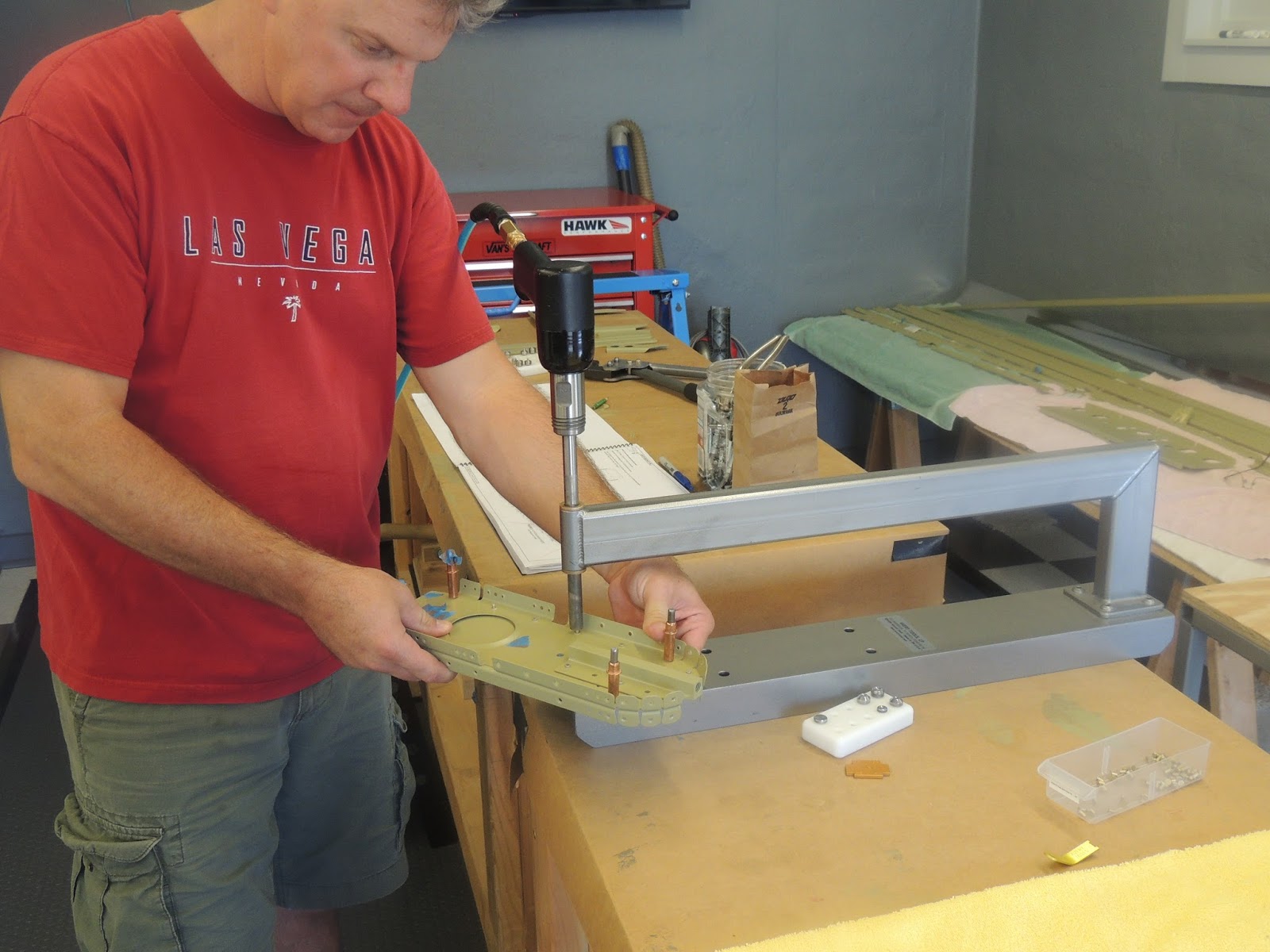
Next, the aft HS attach bars get final drilled to its associated bulkheads. As I mentioned previously, when drilling in thicker material, it is especially important to drill perpendicular to the parts. In this case, I used a drill bushing that I purchased from one of the online aviation tool suppliers. Side Note: It would probably be easier and possibly more precise with a drill press for these holes. However, I have noticed that my drill press has a very slight "wobble" that would possibly affect the hole quality..especially in the thicker material. Until I get that resolved, I will use my small cordless drill that spins the bit nice and straight. It's just a bit more difficult to make sure the bit is perpendicular to the the material being drilled.
 |
| Holes final drilled #30 for the HS attach brackets and the bulkhead. The holes turned out nice and straight and provide a snug fit for a #4 rivet. |
August 20, 2016
The last few days I've continued final drilling, trimming and machine countersinking the individual pieces of the pieces of the aft fuselage. Because I'm priming, I try and go through the whole section (before priming) and complete any steps which call for drilling, cutting, etc. I also do most all dimpling after priming. Sometimes, as seen in the picture below, I find it easier to follow the plans and assemble the parts as I complete the drilling, cutting, countersinking (with clecos only). Of course, once assembled, everything must be dissembled, deburred and prepped for priming. Kind of a pain for sure, but that's the way it goes when you prime.
 |
| This is the lower aft skin of the tail cone. There is some trimming required here, and because of it's shape, I was having trouble deciding on a way to cut it. It wouldn't fit on the band saw, and it's too thick to use metal shears. There's probably a better way, but here's what I did and it worked ok. |
 |
| I rested my hand on the skin for stability and just went very slowly. Potential for screw up here is "moderate". If the cut-off wheel grabs and jumps off the line , it could do some damage very quickly. I kept the speed of the dremmel as low as I could, moved slowly, and made several shallow cuts until the blade was all the way though the metal. |
As I mentioned above, I like to assemble the pieces (when able) as I drill, shape, etc. It's nice to see how everything fits together, plus it's kind of fun.
 |
| Here's some of the pieces of the aft fuselage assembled (clecos only) for drilling, shaping, etc. It's nice to see the "big picture" before I assemble for real with rivets later on. Unfortunately, I now have to dissemble and start the de-burring process and prep for priming. |
August 22, 2016
Got plenty of practice today with machine countersinking. There are two longerons that run along each side of the upper portion of the aft fuselage. Because they are too thick to dimple, they must be countersunk. The outer skins of the fuselage will be riveted to these later with flush rivets.
 |
| Here's the setup I used to machine countersink the #40 holes in the aft fuselage longerons. I have learned from "experience" to be very carful when countersinking. I have gone to deep a couple times in the past. I continually check the depth with a #3 flush rivet and make adjustments to the countersink stop as required. |
 |
| The longerons with all 288 holes countersunk! It took about 3 hours, but all holes turn out very nice. |
August 31, 2016
With most all of the prep work for the Aft Fuselage parts complete (match drilling, countersinking, etc.), it's time to DEBURR! So far, in my build process, the Aft Fuselage parts have taken the most time to complete this task....by far. There are several parts with small tabs, irregular shapes, and LOTS of holes. I spent probably around around 15 hours deburring all these parts..and that's a conservative number. I listen to the radio (news, music, talk radio) most of the time while I work. During this duburring marathon, I got tired of it all. You can only take so much of Hillary and Donald:) I think next time I may visit the library and get a book on tape. A hotel van driver I talked to at work this week says he listens to civil war history. I will give that a try.
 |
| This is all the parts (minus the skins) for the Aft Fuselage after deburring. Lots of time spent on these. Not my favorite part of the build, but you just suck it up and work on one piece at a time. Next up is priming, and then I start the fun part again...putting pieces together and driving rivets. |
September 4, 2016
It took me several hours ,over three days, to take the parts above from bare aluminum to a pretty green color. I'm not sure it's worth it. My next RV build, I'll probably just prime the parts that Van's recommends and move on. Nah....I'm a glutton for punishment, I'd probably do it all over again:) Actually, the priming isn't the bad part..,it's the prep before priming. I'm prepping the aluminum Alclad surface using Prekote and a maroon scotch brite pad. The large parts aren't too bad, but small parts with a bunch of nooks and crannies can be a pain. I would probably use the acid/alodine method, but I'm trying to stay somewhat environmentally friendly...and healthy, especially since I live in a neighborhood with other folks living nearby.
 |
| Here's all the pretty green parts of the Aft Fuselage. Ready to start dimpling and riveting now...finally:) |
September 5, 2016
The family was out of town, so I got to spend several hours out in the shop today. With all the parts primed, it was time to return to the beginning of the Aft Fuselage plans instructions and start the assembly process. Remember, I skip ahead through the plans and try to complete as much of the trimming, drilling, countersinking, etc., as possible before the parts are primed. I'm careful to check off with a green pencil the steps that I complete to keep the confusion to minimum when I come back later after parts are primed. I also dimple when possible after priming. The aft fuselage assembly begins with the most aft bulkhead and work forward. There is quite a bit of dimpling in the flanges and webs of these bulkheads. However, there are several holes that remain un-dimpled so we were careful to read each step a couple of times and verify the dimpled//un-dimpled holes and also the direction of the dimple. I believe we got everything correct. We may not know for sure until other parts and skins get added later.
 |
| Here, neighbor Scott and I use the C-Frame to back-rivet two bulkheads together to form one of the aft bulkheads of the plane. (Scott is back in the game after completing a bathroom re-model that limited is RV building time:) |
 |
| Better picture of the aft bulkhead. This also shows the tie-down bracket that is riveted, and bolted to this bulkhead. An eye-bolt will be threaded into this bracket later and used to tie down the tail of the plane. |
 |
| Scott's daughter came over to help today as well. She's a fast learner and did a good job of inserting the rivets in the holes and taping in place before riveting. However, I think she was a little disappointed at the end of the day when we weren't able to go flying:) |
 |
| Lots of dimpling on these bulkheads. We were able to use the DRDT-2 for most, had to hand squeeze some. Like I stated above, pay very close attention to the plans to make sure the correct holes get dimpled, and in the right direction! Hope we got them all correct or we'll find out later when something doesn't fit properly. |
 |
| Here's three of the aft bulkheads after riveting. We didn't find any guidance on rivet direction in the plans, so we went with the standard practice of trying to keep the manufactured head on the thinnest material. This picture shows the shop heads. I think our rivet orientation worked out well, especially on the thick horizontal stab attach brackets. |
 |
| Here's the same bulkheads showing the manufactured heads. |
 |
| The bulkheads get larger as we work our way forward. Not much riveting here other than a few rivets to join the bulkhead pieces together. Like the other bulkheads, all the holes in the flanges of these get dimpled to match the dimpled skin and flush rivet head later on. |
 |
| This is a cover plate for an access panel between the most aft two bulkheads. The plans give you the option to either use the round-head screws that come standard, or to dimple and use flush screws. Also, if the flush option is chosen, there is a few small changes that need to accomplished..different nut plates, extra, dimpling, etc. The plans show both options. I decided to use the round head screw option. Not because it is probably a little easier, but because I think I may be able to get the plate to fit a little "tighter" to the skins using this option. My thinking is that the dimpled option may prevent the plate from sitting completely flat on the skins. I could be wrong. I haven't had to chance to see either option in a finished plane. |
Overall, today was a fun and productive day and, most importantly, no mistakes (that I know of):) Let's see how long I keep that trend going!
September 6, 2016
Didn't plan on getting much time to do any RV work today, but had some time in the afternoon and was able to get in a few hours. Then, after dinner neighbor Scott texted and asked if I planned on doing any work tonight...I couldn't say no and disappoint him:). It turned out to be a productive day. I'll try and cover most of what I did in the pictures below.
 |
| Started today by riveting nutplates to the battery angles, and then the angles to the bellcrank rib. I used a hand squeezer to set these rivets . I used the yoke in this picture to set the rivets for the battery angle to the bell crank rib. For the nutplates, I used a regular "small throated" C shaped yoke. |
 |
| Final product of the bellcrank ribs and battery angles. |
 |
| Here's the forward bulkhead after holes dimpled and nut plates installed. All the nutplates, except the two with offset holes, have factory dimpled attach holes. |
 |
| I used the c-frame with flat rivet sets to set the flush rivets for the nutplates. |
 |
| Here's the two nutplates with the offset holes from the picture above. The rivet holes for these were not factory dimpled. I dimpled using the DRDT-2. Per the recommendation in section 5 of the plans, I used a reduced diameter female die so as to not damage the raised portion of the nutplate. |
 |
| Nutplate being dimpled with reduced diameter female die and DRDT-2. Notice the minimal clearance between the die and the raised portion of the nutplate. |
 |
| After the nutplates get installed, the big pieces start going together pretty quickly. First, the bellcrank ribs get riveted to the rectangular shaped forward bulkhead. I don't have pictures, but we used a rivet gun and bucking bar to set all but the four that were reachable using a longeron yoke. I wanted to put the manufactured heads on the flanges of the bellcrank ribs, but the plans state to place the manufactured heads on the forward portion of the bulkhead. Probably a good idea anyway, it would have have been slightly more difficult to place the manufactured heads on the flange side and would have required using an offset rivet set. |
 |
| Better view of the forward bulkhead. |
 |
| We did have one small issue. (This is Step 1, page 10-13 for reference) This picture shows the aft side of the large oval bulkhead looking forward. The six rivets outer rivets in this picture attach the bulkhead to the bellcrank ribs. I clecoed the parts together and decided to put the manufactured universal head of the rivet on the flange of the bellcrank rib. This is standard practice when possible, and it seems to "pull" the flange tightly to what ever it is being riveted to. However, what we ended up with, as seen in the picture, was four rivets with the universal head on the bellcrank flange side, while the other two are reversed. What happened here was we used the longeron yoke and started with the rivets in the center of the bellcrank flange and worked outboard. When we got to the last two rivets, we had a space issue due to the battery angle and the most aft rivet (shop head) used to secure it. The squeezer yoke would not fit. We then tried using an offset rivet set and rivet gun. The offset was close, but it was on the universal rivet head at just a slight angle and I was worried that it may cut the the bellcrank flange and possibly put a smiley on the rivet head. The only option we could come up with was to reverse the orientation of these two rivets. We did, and were were then able to use the straight rivet set and gun with a narrow tungsten bucking bar on the flange side. |
 |
| Here's the bellcrank flange view of what was explained in the picture above. I don't think there is any issue here other than aesthetics. The picture is a little deceiving, it looks like the nut plate might have been causing the obstruction issue, but it was actually the last rivet on the battery angle (behind the nutplate in picture). I just mention it here so future builders can consider this when they get to this point of their build. |
So, once again, a pretty rewarding and productive day considering I was only planning on riveting a few nutplates . It will be a few days before I get a chance to do anymore building, but next up is getting the aft fuselage skins de-burred, primed and then dimpled in preparation for adding them to the aft fuselage assembly.
September 9, 2016
I had some time today, so I decided to deburr, prep and prime the Aft Fuselage bottom skins. Pretty easy deburring compared to all the other parts I've been working with lately. I let the primer cure for a day and then dimpled all the #40 holes using the DRDT-2.
 |
| This is the Aft Fuselage lower skins after priming and getting dimpled using the DRDT-2. Make sure to use a reduced diameter female die (as stated in the plans) along the side edges to avoid possible damage to the pre-formed rolled edges of the skins. Deburring, priming, and dimpling pretty easy on this compared to the smaller parts I've been working with lately. |
 |
| J-Stiffeners also got dimpled. I used the DRDT-2 where I could, but had to use the hand squeezer in some locations. The longerons are next to the wall. The holes in those were machine countersunk earlier. |
September 14, 2016
I got home early afternoon from a work trip and was able to get a few things done today. I'm ready to begin initial assembly of the Aft Fuselage. The plans recommend placing the skins upside down on saw horses and assembling the Bulkheads and J-Stiffeners to the lower skins. I assembled the parts with clecos to develop a plan of attack for the riveting. I did notice three rivets that may be difficult to set if not done in a certain order. I will point those out later.
 |
| Here's the setup I'm initially using to get the Aft Fuselage assembled. The plans recommend placing the skins upside-down on saw horses. I used one saw horse and the edge of my workbench. |
 |
| The J-Stiffeners are slid through the forward bulkhead and then the aft bulkhead gets slid along the j-stiffeners into position. The plans indicate some bending or trimming may be required to get these parts in position, but I didn't have any issues. This can kind of be like a puzzle, but everything fits together nicely I think if the plans are followed step by step here. |
 |
| No riveting yet, but here's the aft-fuselage skin with the initial bulkheads and stiffeners in place. |
 |
| The blue tape marks off areas that do not get riveted at this time. In my experience so far, I find the tape is the safest thing that prevents me from riveting unwanted holes. When you get in the groove riveting, it can be easy to overlook if the holes are not clearly marked. |
September 15, 2016
Today I started riveting J-Channels and Bulkheads to the aft-fuselage skin. I used different riveting methods depending on the situation. Additionally, because I was solo today, I did a few things differently than if I had a bucking partner. I stated earlier that there were three rivets that might be difficult to access for riveting. I will show these in the pictures below. As shown above, I did have the Aft-Fuselage assembly clecoed together and hanging upside down on saw horses as the plans describe. However, I ended up disassembling and riveting parts a little differently than the plans show. One of the things I did was to use the C-Frame to rivet the j-channels to the skins. Probably a little different, but I think it worked out well. Then, after setting the two difficult to access rivets on a bulkhead, I once again clecoed the parts together and hung upside down on saw horses. The riveting at that point was pretty standard using the spring-loaded back rivet set mostly and the occasional bucking bar.
 |
The pictures above and below show the rivets that I thought might be difficult to set. In the picture above, it is the last rivet in the j-channel. It is somewhat obstructed by the rivets of the cable guide making it tight for a bucking bar or back rivet set. After, reviewing the plans carefully, I decided that I could rivet the j-channel stiffeners to the skins prior to attaching the bulkhead. See description below.
The picture below, shows a rivet (indicated with blue tape) that secures bulkhead F-01407 to the lower skin. However, once the j-channel is riveted in place, that rivet would be difficult to access. There are two of these rivets. One on the left j-channel and one on the right. Again, after careful review of the plans, I decided that I could set this rivet with the j-channel removed and then slide the j-channel back in position. You have to be careful doing things out of sequence like this can be sort of like a puzzle where some pieces won't fit once others are in position. |

 |
| Here, I'm riveting the j-channel to the lower skins using the c-frame. This will take care of the first difficult to access rivet mentioned above. However, this is a little different than the plans describe, and probably not the way most builders accomplish this step. I guess I just like using the c-frame to back rivet when possible. It's kind of like my security blanket though, and I will eventually have to dust of the old bucking bar:) |
 |
| You can see I had to elevate the skin to match the height of the c-frame. |
 |
| Here's the J-Channels riveted in place on the lower skins. |
Next, I wanted to set the two other difficult rivets located on the forward bulkhead that will have limited access due to j-stiffeners. At this point, I still have the assembly upright, and have not hung upside down as the plans describe.
 |
| Here's the right side rivet on F-01407 that has limited access due to the right j-channel. (The same situation applies to the left side) In this picture, I have not yet riveted the j-channle in place. I have it temporarily in place for reference. |
 |
| Here's the same rivet as described in the picture above. The j-channel was removed and the rivet was set using rivet gun and bucking bar. I know.....the rivet is "slightly" over-driven, but I'm not touching it:) The left side turned out much better..I promise! |
Once these rivets were set, I reverted back to assembling the structure following the plans and once again hung it upside down on the saw horse.
 |
| Once I had the structure back on the saw horse and upside down. I started riveting the two bulkheads that are clecoed in position. Most of theses rivets were set using a long spring-loaded back rivet set and large bucking bar as shown in the picture. I like using the spring-loaded back rivet set here because it helps to hold the flanges tight against the skins when riveting. This is especially important when riveting pieces like this solo, and you're not able to hold the flanges tight with your fingers. However, there were places where I had use normal riveting using rivet gun with large "swivel mushroom" set and small tungsten bucking bar. I had three rivets today that I wasn't happy with and drilled them out. The replacements luckily went in nicely. You never know about those "second timers":) |
 |
| Difficult to see in the picture, but there are a few less clecos. Today I completed the riveting for both the forward and aft bulkheads and the two aft j-stiffeners to the lower skin. Remaining to rivet are the long, left and right, j-stiffeners, and the lower flanges of the bell crank assembly. |
 |
| Here's the tools I used today. I only used the back rivet plate for a few rivets on the aft j-channels and then switched to the c-frame. The long spring-loaded back rivet set is meant to be used with the c-frame. However, I used it today with the rivet gun to set the rivets on the flanges of the bulkheads. The shorter back-rivet set I have was causing the gun to make contact with the opposite flange of the bulkhead. |
September 17, 2016
Once again, I did't plan on getting any RV work done today. A "simple" toilet repair project turned into almost an all day deal. However, I had a few minutes before my wife and I were going out to dinner so I went out to to the shop to just plan ahead, and the next thing you know I had the rivet gun in hand. I started riveting the rivets of the bell crank rib to the lower aft fuselage skin. There may be other options, but the plan I came up with for these rivets was the rivet gun and bucking bar. These rivets are almost down the centerline of the bottom skin and I was not happy with the rivet quality I was getting holding the rivet gun and bucking solo. With my go-to rivet partner (neighbor Scott) out of town, it was time to give my wife some rivet gun experience! While not thrilled at first (I think she was a little worried about messing something up), she reluctantly agreed to give it a try. I gave her a short intro to rivet gun basics...hold it straight, feather the trigger, etc., and then we went right to work with no practice. It started pretty slowly as she got the feel for the rivet gun, but after about ten or so rivets, our pace picked up. I was pretty happy with our progress, but since we had dinner plans, I thought that would be it for the day. Well, after dinner I stepped out to the shop to review our work and, since my wife was just outside the shop watering plants, I thought it couldn't hurt to ask:) She agreed and within about 30 minutes we finished all the rivets for the bell crank assembly to to the lower skins. I actually think she may have enjoyed it...although too early to tell and I don't want to push it:)
 |
| My wife, after a little encouragement, agreed to help me drive some rivets. The rivets that attach the bell -crank assembly are down down the center of the skin and are much easier to buck with a helper. While reluctant at first, I think she may have actually enjoyed it. |
 |
| The rivets for the bell-crank assembly are the two rows down the center of the skins. The remaining rivets (shown by clecos), are for the j-chaanels that run the entire length of the skin. I may back-rivet these using a back-rivet plate and the spring-loaded rivet set. I'll have to think about that a little more though. |
 |
| This is the underside of the skins showing the shop heads of the rivets that attach the aft fuselage skin to the bell-crank assembly. |
September 18, 2016
Today I riveted the remaining two j-stiffeners to the aft-fuselage skins. I was debating about how to rivet these and was leaning towards using the back-rivet set and plate. However, since the assembly was still upside down on the saw horse, I started setting the rivets with the spring loaded rivet set and large back-riveting bucking bar. These rivets were turning out pretty good. However, working solo, I was moving fairly slowly and thought I would switch to back-riveting. I put the aft-fuselage assembly upright on the tables and set up for back-riveting. One thing to consider if going this route is that the bottom skin at this point isn't completely flat. It has a very slight "canoe" type bottom due to being riveted to the two bulkheads. After putting the back-rivet plate in place under the skins, I made sure to "level" the skin on the plate by placing towels under the opposite side skin. As the riveting progressed, I had to keep moving the plate and leveling the skins. The back-riveting turned out well, but did require a fair amount of set-up.
 |
| This is the aft-fuselage skin with the rivets for the j-stiffeners in place for back-riveting (the center two tape lines). I didn't have rivet tape, so I used the blue painters tape. |
 |
| I tried a variety of the back-rivet sets, but found the long non-spring set was working best for me. I was working solo, so I was,t able to get a good picture. Here, I'm just showing the rivet gun and set I used. The back-rivet plate is under the skin. The note reminds me to MOVE THE PLATE. I've heard "some people" have forgotten to move the plate when back-riveting:) Not today! |
 |
| Because I was not using the spring-loaded rivet set, I make sure to hold the j-channel nice and tightly to the skin. It also serves to keep the link rivet set in position and secure. |
 |
| Here's the three back-rivet sets I experimented with while riveting the j-stiffeners to the skins. All worked pretty well however, I seemed to have better luck with the long, non-spring loaded version. Your results may vary:) |
 |
| This is what I ended up with at the end of the day. |
September 15-20, 2016
Next up is installing the side skins. The plans advise to skip a few pages ahead and get familiar with some wiring and systems that need to be installed. The reason is that some of the wires have pre-installed connectors that will not fit through the bulkheads as required once the side skins are installed. I pretty much just went ahead and installed all the wiring prior to clecoing the side skins in place. However, I also got a little carried away and final (I thought) zip tied all the wires in place and made them look real nice and neat. Unfortunately, for various reasons...even to include riveting the skins later own, the wires will probably need to be moved or adjusted as the side skins are put in place. Because of this, I will probably have to remove and replace most of the zip ties I installed. Just do what the plans advise and get the wires in place and secure temporarily until the sins are on and riveting complete.
I hadn't yet primed the side skins, so that was up next. There is one thing to be aware of with the side skins. They overlap the bottom skin and the plans say to put a slight break in the edge of the side skins so they will fit tight against the bottom skins. There are a few different ways do accomplish this "break", but all need to be accomplished prior to dimpling. So, after I primed the side skins, but prior to dimpling the hole, I put the slight break in the edges. I will discuss this more in the pictures below.
 |
| This is right side skin for the aft fuselage. The curved potion of the skin will overlap the bottom skin that has already been installed. That is the edge that has to have a slight "break" so it will fit tight against the bottom skins. |
 |
| Here are the two tool that I have available to accomplish the slight breaks in the skin edges. They both accomplish the same thing, so it is builder preference as to which one to use. Most seem to prefer the vise grip style tool. However, in my limited experience so far, I seem to prefer the tool on the left. No matter which tool you use, be careful to not over do it. The break should be very slight. Barely visible by looking at it. From what I've read, and personal experience, if you over do it, you can stretch the skin making it have a slight "wave". Probably a good idea to practice on scrap with these if possible. |
 |
| Once the skins were primed, it was time to dimple. For the majority of the holes, I used the DRDT-2. Some holes in the curved portions of the skins require the use of a reduced diameter female die. The holes along the bottom curved edge, I used a hand squeezer to dimple. Take your time here, there are holes that don't get dimpled. Keep in mind during this step the holes for nutplates are not #30 holes. They are slightly larger..#27 I think. Also, because the plans give the option to use flash screws around the square access panel shown here, some builders will need to dimple these hole and others will not. I am not going to use the flush screws, so no dimple the nutplate holes. |
 |
| These pictures show some of the initial wiring that needs to be installed prior to the skins being installed. The wires lay in the channel of on of the stiffeners that run fore/aft. The wires need to be installed now, because some of the pre-installed plugs will not fit through some if the bulkheads once the skins are installed. One other note here...there are several plastic bushings that need to be "slit" and wires installed before they are snapped in place. I snapped all in place, but had to remove several due to the wire connectors not fitting through. |
 |
| The rudder cables are also installed at this time. |
 |
| Here, the side skins are clecoed in place and checked for fit. Good time to double check all dimples are correct and bottom edge of these skins fit tight against bottom skin. |
 |
| There is one more bulkhead and short piece of lower skin that gets attached to this aft portion of the fuselage. |
 |
| This is the most aft section of the fuselage. Here the bulkhead and lower skin are clecoed together ready for riveting. |
 |
| The tab type flanges of this bulkhead needed to be adjusted slightly to ensure a tight fight with the lower skin shape. I decided to squeeze these rivets so I could use the rubber washer trick to ensure the flanges stayed tight with the skin during riveting. The rivet being squeezed in this picture was the most difficult because of the location of the tie down hook bracket. Future builders might consider leaving the tie down bracket off until these rivets are set..especially if using a squeezer. I don't see any obvious reasons why that couldn't be done, but study closely to make sure before making that decision. |
 |
| These are the rivets on the flanges on the aft side of the most aft bulkhead. The plans call for 3.5 rivets here, but they measured a little short so I used 4s instead. I've noticed Van's sometimes will err on the side of a shorter rivet when the longer river may be more difficult to set. I'm sure the engineers have done the math and the shorter rivets are more than adequate. However, these rivets are pretty easy to squeeze, so I used the longer rivets. Also in this picture, I am using the rubber washer trick to ensure the tab type flanges stay tight against the skin during riveting. I got these washers from the plumbing section of the hardware store. They are a soft type of rubber that will "squeeze" with slight pressure. The goal is to stack enough washers on the rivet shank to be just a bit taller than the rivet. When the squeeze is applied, the the rubber compresses first and presses down on the flange. As more pressure is applied, the squeezer head makes contact with the rivet. The rivet is then just slightly set until it is able to hold the flange down on it own. The rubber washers are then removed and the rivet is then final squeezed. |
 |
| Here's the finished product of the longer -4 rivets from the description above. |
 |
| This is the aft fuselage skin and bulkhead assembly ready to be installed on the aft fuselage. |
Today I clecoed and started riveting the aft fuselage skin and bulkhead assembly. The initial riveting is the lower flanges of the bulkhead just forward of the most aft bulkhead. These flanges, especially the ones on the aft side of this bulkhead are in fairly tight quarters. The rivets have to be set using rivet gun and bucking bar.
One issue I also discovered after clecoing the assembly in place is that I have a slight issue with the side skin fit against the lower aft fuselage skin. I put the slight break in the side skins prior to dimpling, but did not place the aft fuselage assembly in position to check for fit. There is a little more of a gap than I like, but it will be difficult to "re-break" thesis skin edges with the holes along the edges now dimpled.
 |
| Here's the Aft Fuselage Bulkhead and Lower Skin Assembly clecoed in position. |
 |
| Looking down on the aft bulkhead assembly. The initial riveting for this assembly are the rivets on the forward and aft sides of the bulkhead that has the attach brackets for the horizontal stabilizer (ears sticking up). These rivets have to be set using a rivet gun and bucking bar. The rivets on the aft side of this bulkhead are in pretty tight quarters. A riveting partner here is very helpful. The plans state to start with the center rivets and work your way out. We did this and the first few rivets aren't too bad. However, as you work for way outboard, the radius of the lower skin gets tighter and bucking bar positioning becomes more difficult. We were using a small tungsten bucking bar with a slight angle across one end (see picture below). We just couldn't get a good angle on the rivet head using this bar for the last couple of rivets in this area. I looked at some different bucking bars online and found what I think will work better. It's basically the same size as the one I have, but the angle on the end is on a different plane. We held off on these rivets and I think I may have a new bucking bar in the near future. I think it will also come in handy throughout the build. |
 |
| Here's a view looking aft at the bulkhead assembly. The lower rivets on the forward side of this bulkhead aren't too difficult to set using a rivet gun and bucking bar. A rivet partner is also a big help! |
 |
| Here's the skin fit issue that I mentioned above. The side skins overlap the bottom skins and the lower aft fuselage skin shown in this picture. A slight break is applied to the side skin lower edges to ensure a tight fit when in position. The side skin to bottom skin fit is good. However, as seen in this picture, the fit with the aft fuselage skin is not very tight. To make this fit better, the break on the edge of the lower skin in this area would have had to been much more than slight. Also, it looks like the break would need to be above the rivet line slightly to match the contour of the lower skin in this area. At this point, since the skins are now dimpled, it would be difficult to increase the break on these skins. I may try to do some type of additional forming, but I don't want to make it worse. I may just set a few rivets and see how it turns out. |
 |
| Here's the small tungsten bucking bar we used for the riveting mentioned above. The left side of the bar above has a slight angle which can be very useful. However, for a few of the rivets, we couldn't seem to get good placement due to the radius of the skin. I found a bucking bar online that has the angle on the end same as this one, but on a different plane that I think will work much better. |
October 8, 2016
Today we started riveting the side skins to the longerons, stiffeners, and bulkheads. The plans state to begin riveting at the top of the skin and work down in order to achieve a tight skin to skin fit with the bottom skin. We followed this advice and started riveting the skins to the longerons first. We squeezed these rivets using the special yoke that allows access around the flange of the longeron. I am lucky to have this yoke on loan from friend Mark. I have used this tool many times during the build.
 |
| Here's neighbor Scott squeezing the rivets for the top skin to the longeron. We were able to use this for almost all the rivets here. There were a few around the bulkheads that we did have to use a rivet gun and bucking bar. |
 |
| The plans call for 3.5 rivets in this area. However, the 3.5's measured just a little short and we decided to use 4's for the skin to longeron riveting. These rivets are pretty easy to set using the squeezer and special yoke, so we had no problems getting a nice shop head using the longer rivets. We switched back to the 3.5 rivets once we moved off the longeron and down to the thinner stiffener to skin riveting. |
October 9, 2016
Once we completed the riveting along the top portion of the side skins, we started working our way down as advised by the plans. We are no longer able to squeeze the rivets, so it's back to bucking. After reviewing other builders sites, it seems that most prefer (where possible) to use back-riveting here using the spring-loaded rivet set and large "barbell" type bucking bar, although I did see a few that rolled the assembly on its side and back-riveted using a back-rivet plate.
Most of the rivets here on the upper portions of the skins could possibly be bucked solo. However, having a partner here is a big help and greatly decreases the chances of damaging the side skins.
 |
| After setting a few rivets with the aft-fuselage in the upright position, we decided to flip it upside down and see how that worked out. We preferred upside down and continued riveting in that configuration. One person is inside using either the spring-loaded back rivet set or small bucking bar depending on the location. |
 |
| View from inside the upside down aft fuselage assembly. Plenty of room in the forward portion for the person inside to manage the back-rivet set or bucking bar. Space gets tighter as you move aft, and we will probably have to get the most aft rivets when we flip the assembly back in the upright position. |
 |
| Still a few more rivets to set:) |
October 10, 2016
I mentioned above that I rotated the aft fuselage upside down to make it easier to set the side skin rivets. That plan included using a rivet gun, the barbell type bucking bar, and a partner. Well, I had two out of three of those requirements, but I did't have the partner. Neighbor Scott was at work and my wife apparently had better things to do:) . So it was time for plan B. I mentioned above that some builders set these side skin rivets by placing the aft fuselage assembly on it side and back-riveting using a back-riveting plate. Well, I decided to give it a try. Working solo, one of the issues was rotating the assembly from the upside down position to its side. While the assembly is not very heavy, it is awkward to get a good hold. Also, because it is not fully assembled yet it is still slightly flimsy and I didn't want to cause any damage. Eventually, by adjusting my work tables and saw horse around I was able to make the move without too much actual lifting. Mostly just spinning and rotating.
 |
| Here's the Aft- Fuselage assembly back in the upright position with rivets and rivet tape in place ready for riveting with back-rivet plate. |
 |
| This is the piece of cold-rolled steel that I will use as a back-rivet plate. I also used this when riveting the trailing edge of the rudder. Once the steel is in place under the skin, I use cardboard strips to shim the skin level with the thickness of the plate, |
 |
| Back-riveting using the back-rivet plate is a quick and consistent way to set rivets. It does require a bit of set up, but once you start riveting it goes very smoothly. However, as I've mentioned several times before, and I have to remind myself constantly....always make sure the back-rivet plate is under the actual rivets you are setting. Potential exists to ruin your day very quickly here. |
 |
| Clecos are starting to disappear. |
October 12, 2016
The process of riveting the side skins of the aft-fuselage continues. There are a few rivets in this assembly that are not easily accessible. The most challenging are in the most aft bulkhead section, but there are a few under j-stiffener and bulkhead flanges in other areas as well. My riveting process changes by the minute, but I think (at the moment) I prefer the short spring-loaded rivet set matched up with the dumbbell type bucking bar. However, this method can't be used for all rivet locations and there are areas where a variety of other bucking bar shapes come in very handy.
 |
| I have bounced back and forth on my riveting techniques for the skins of the aft fuselage. I seem to be getting the most comfortable and consistent results with the combination in the picture above. However, there are several areas in the aft fuselage where other riveting techniques and bucking bar shapes and sizes are better suited. I don't have a pictures tonight, but I will try and get some pictures of some other "nice to have" bucking bar shapes that come in handy for the aft- fuselage. P.S. Pay no attention to the aluminum shavings. I can neither confirm nor deny that they are possible remnants of drilled out rivet/s. :) |
 |
| Here's the bucking process using the spring-loaded rivet set and "barbell" bucking bar. Once you get the hang of it, this produces very consistent results. |
 |
| Here's my selection of bucking cars so far. When space permits, I like using the tungsten bar on the right. However, due to the limited space in the aft-fuselage, I found myself using the other ones much more. The tungsten bar in the middle was the one I think got used the most when not back-riveting. |
October 14-17, 2016
The riveting continues on the Aft-Fuselage. There is a little more involved here than I expected. Especially the aft section where space is limited, and the angles between bulkheads and skins can make setting certain rivets very challenging. One rivet at a time is the way to go here. I spent some extra time on the difficult rivets deciding on the best bucking bar choice, and ways to position without damaging skins and surrounding rivets during the bucking process. I found that it was actually easier to buck the rivets in the most aft bulkhead areas solo. I could get a better feel on the bucking bar position and have better control when I pulled the trigger on the rivet gun. However, as you move forward in the larger areas of the fuselage a bucking partner is almost a requirement. You could roll the assembly on its side and back rivet using a plate, but as you get to the curved portion of the lower skins this would become very challenging...for me anyway:) I am lucky to have neighbor Scott close by and he is always willing to help when he is available.
 |
| This is aft portion of the fuselage. Setting rivets inside this area can be challenging due to limited space and angles of the bulkheads preventing optimum bucking bar placement. |
 |
| This view is looking down at the most aft "compartment" of the fuselage. You can see the top of the tie down bracket in the very bottom of the picture. There are two rivets on each side of the bulkhead in the upper portion of the picture that were a little challenging for me. They are on the curved portion of the bulkhead just under the stiffener angle (not visible in picture). Due to the radius of the skin in this area and the fact the bulkhead leans back, I had trouble getting a bucking bar in the proper position. I have some small tungsten bucking bars, but the angles were not quite right. I ended up ordering a new tungsten bucking bar with an angle that would work much better. However, when it showed up, it was a little narrower than I'd planed on. It fit very nicely for the areas I needed, but because it is slightly more narrow than I've used before I was worried about it slipping off the rivet head when bucking. I decided that this bucking bar was my best option though. I was able to get a nice hold on the bucking bar and use my fingers to support/hold it in position while riveting. Surprisingly, the rivets turned out pretty good. |
 |
| This is the view looking back of the bulkhead in the picture above. The rivets in this area are a little easier to set due to a little more space. However, the ones under the j-stiffener are not visible and you just have to go by feel. I used my small square tungsten bucking bar that fits easily in my palm and was able to get pretty nice rivets here. You will have to use a mirror to check on these after setting. |
 |
| This is the view looking up at the lower skin of the aft-fuselage. Tie down bracket hole is visible here. I mentioned in one of my posts earlier that In was a little concerned about the side skin to lower skin fit in this area. I was worried that I may not have put enough of a break in the side skins to provide a tight fit with the bottom skins. However, after riveting these skins together, I'm happy with the results. |
 |
| Once I finished with the riveting in the aft bulkhead section, we flipped the aft-fuselage upside down to continue riveting towards the bottom or curved portion of the side skins. We are primarily using the spring-loaded rivet set and "barbell" shaped bucking bar for back-riveting on the skins in this area. However, there are a few rivets under stiffeners and bulkhead flanges that still need to be bucked. |
 |
| Here, neighbor Scott holds the "barbell" style bucking bar against the manufactured head of the flush rivet while I operate the rivet gun with spring-loaded rivet set on the shop head of the rivet. Back-riveting is a very efficient way to rivet the skins and less likely to damage the skins, but there is a learning curve here as well. It can be difficult to set a perfect shop head on the inside portion of the dimple. They have a tendency to lean slightly off the dimple if the gun is not held at the proper angle or the air pressure is not set correctly. With all the practice with the bucking bar lately, I could probably get a more consistent, better "looking" shop head using a rivet gun and bucking bar. However, I do like the way the spring-loaded back rivet set holds the flanges tight against the skins while riveting. Just takes practice and a good aim when using the spring-loaded set I guess. |
October 19, 2016
The riveting for the Aft-Fuselage side skins is complete. Mostly happy with the rivets but there are a few that aren't perfect. We did use two oops rivets because of slightly enlarged holes when drilling out "bad" rivets. Interestingly, the rivets that were in the difficult locations turned out pretty good. I think because we really took our time and planned for those. It's the ones that should have been easy that I got sloppy on. This was mostly when using the spring-loaded back rivet set. I think you get on a roll because it is pretty easy and maybe move a little too quickly. No major issues with those few rivets, mostly just "leaned" a little bit on the inside dimple. When using the spring-loaded back rivet setup, it's important, and sometimes not that easy, to keep the alignment on the rivet shank perfect or the rivet will lean a bit. As mentioned above, I've had much better luck lately bucking rivets and, looking back, there are a few that I should have bucked instead of back-riveted.
 |
| Most of the clecos have disappeared on the Aft-Fuselage side skins. Still have few things to rivet in the aft section (areas with blue tape)...Nut plates, two small angle stiffeners, and the the two rudder stops, before moving on to the next step. |
 |
| Another benefit I think of setting some of the skin rivets using the spring-loaded back rivet set and "dumbbell" style bucking bar is good skin/skin contact at the joints. We ended up with very tight skin contact at the joints and I believe it was largely due to the back riveting. |
October 30 - November 4, 2016
With the skin riveting complete, it was time to finish up some miscellaneous riveting in the most aft section of the fuselage. This included installing several nutplates, the two rudder stops, and two short angle stiffeners. The nutplates are all pretty easy to install and I believe I was able to use the squeezer to set all the rivets for those. However, when installing the short angle stiffeners and the rudder stops, it is pretty tight quarters for a few of these rivets and it's best to come up with a plane before you start. The plans say to install the rudder stops before the angle stiffeners. However, after I clecoed the angle stiffeners and rudder stops in place I noticed one rivet on the lower part of each angle stiffener would be difficult to set with the rudder stops installed. I looked at all the options I had given the bucking bars I had, and I decided to install the angle stiffeners before the rudder stops. There were still a couple of rivets that were pretty tight when I did install the rudder stops, but I was able to my small angled tungsten bucking bar to set those. I think my plan worked out pretty well, but following the plans might work just as well depending on your available tools and preferences.
 |
| Here's a few of the nutplates that get installed in the aft section of the fuselage. These are located between the last two bulkheads. A few are used for the screws that attach two access panel panel cover plates. The plans gives the option to dimple the plates to be able to use flush screws. I opted to stick with the round head screw option, so some of the these pictures will look different if you choose to go the flush screw route. One other small note here is that the plans state where and where not to use dimpled nutplates. In this case I am referring to the rivet holes getting dimpled and not the hole for the screws. There is a small error in the plans (at my build time), that states to use dimpled nutplates for the access panels. However, there are two each side that do not need to be dimpled. They are actually visible in this picture. The two in the upper part of the photo do not require dimpling because they are located on the longeron that was machine countersunk due to its thickness. Therefore, there is no dimple on the back-side of this piece. |
 |
| This is the area between the last two bulkheads. The two angle stiffeners I mentioned above are visible on the lower left and right lower portions of the assembly. The rivets in the most lower aft section of those brackets are the ones that are in close proximity to the rivets for the rudder stop rivets. I did the angle stiffeners first as discussed above and then the rudder stop rivets. Look at this area closely and come up with a plan before you fire up the rivet gun:) |
 |
| Mom and Dad came to visit for a few days and got to spend a little time on the RV project. Here Dad operates the rivet gun while I hold the bucking bar while we set rivets on the rudder stops. We were able to use the "mushroom" set for the two lower rivets, but had to switch to the straight set for the upper two due to the angle of the rudder stop. |
 |
| Here's the outside view of the area discussed above. Here you can see one of the reasons I decided to rivet the angle stiffener on before the rudder stop brackets. There is one rivet for the angle stiffener located just below the lower forward rivet on the rudder stop that I though would be very difficult to set without possible damage to skins and/or the rudder stop if you install the rudder stop before the stiffener. I did the stiffener first and it worked out well, but it does make for tight quarters inside when setting the rudder stop rivets. Have a plan for which rivets to set first if you go this route. |
 |
| Rudder stops, nutplates, and stiffeners installed. |
Next up is installation of the rudder cables and guides.
 |
| This picture shows the slots on each side of the fuselage where the rudder cables pass through the skins. |
 |
| Here's one of the rudder cable guides. It needs to be machine countersunk for the dimpled skins. |
 |
| I used the countersink bitand just turned it by hand. |
 |
| The rudder cable guides are fastened to the skins using blind rivets. These are the type of rivets where the shank is suppose to break off and a portion remain inside of the rivet to provide some structural integrity. However, when setting a couple of these, the shank did not break off inside and actually pulled all the way out. Probably would have been ok, but I drilled out the two and set them again using a little different technique. I pulled the rivet until I could see that it was set properly from the inside, and then I stopped pulling. I then, very slightly, "wriggled" the rivet mandrel just to weaken it enough to hopefully allow it to break. I then continued to pull with the rivet puller and the rivet broke off nicely. Also, one other issue I had is that two of the shanks actually pulled out too far before breaking and are sitting proud of the skins. As seen in the photo below, the rudder cable guide are two different thicknesses. I think this caused the issue as seen in the forward two rivets pictures above. I drilled out the two rivets with the mandrels sticking too far out and am going to try using the same type rivets, but with a shorter grip length. |
 |
| Inside view showing the rudder cable guides. Per the plans, washers are placed on the rivets before being set to allow for a better grip of the plastic type material. Here you can see the different thicknesses of the two separate pieces. The two on the right side are the ones where the mandrels broke proud of the skins. I removed them and will try blind rivets with a shorter grip length. I though about just adding a couple more rivets, but will try a different rivet first. |
November 14, 2016
I ordered the shorter (grip length) blind rivets for the rudder cable guides from Vans. The shorter rivets worked out much better. They could have been even a little shorter, but I got the smallest that Vans had listed on their website.
 |
| The blind rivets on the left (AACQ-4-4) are the ones supplied with the kit. As described above, I felt they were a little long for the two thinner pieces of the rudder cable guides. I ordered the shorter replacements (AACQ-4-3) from Vans and they worked out much better. |
 |
| Better view of the different lengths of the blind rivets. |
 |
| I used the shorter rivets for the thinner portion of the rudder cabe guides and they worked out much better. They could have even been a little shorter, but I didn't see any listed on Vans parts site. Could probably add one additional washer if you want, but this setup worked fine. |
 |
Skin side view of the blind rivets in place for the rudder cable guides. The forward two in the picture are the shorter replacements. This time the rivet shanks broke off inside the rivet (as required), and did not protrude proud of the skin.
|
November 18-20, 2016
UPDATE: Feb 2018 - This option wasn't available at the time of my static port installation. I would have probably given it a try. Vans Static Port Kit
I have been delaying putting in the two static ports on the aft fuselage skins because I wasn't sure which method I was going to use. The kit comes from Vans with everything you need to install the system. However, after reviewing several other builders blogs of many types of RV's, I noticed many were using some type of aftermarket static system for these two ports. The Vans system basically consist of two blind rivets, plastic connectors and tubing. Pretty simple, but it works and when installed correctly, will probably never have any issues. The aftermarket kit that most builders seem to be using (at this time) is provided by Cleveland Tools. It also includes everything needed to install the two staic ports in the aft fuselage. However, instead of using the blind rivets as provided by Vans, this kit has two nicely machined static ports that get "glued" with proseal onto the skins. Additionally, instead of plastic fittings to connect the hose/ports this kit includes some nice "push/pull' type fittings and probably a higher quality of static line hose. This method also requires that the small predrilled hole in the skin be enlarged to .5".
Like I said, I was having trouble deciding between which method to use. I liked the simplicity of the Vans system, but also liked the higher quality and looks of the Cleveland system. I was a little concerned about drilling g the .5" hole require for the Cleveland setup.
The Vans system is proven and many seasoned builders prefer it because it works and gives good static inputs to the system right out of the box. Apparently, there was an after market system used before the Cleveland product was available called "SafeAir". Again the product was very nice quality, but several builder noted pitot static errors (airspeed/altitude) when using this product. This product sat completely flush with the skin and many builders determined this could be the problem Many solved this by attaching a "cut off" blind rivet head too the exterior skins. This seemed to work. The Cleveland product appears to have solved this problem by protruding the port from the skin to match the dimension of the blind rivet head used by Vans. I haven't heard any issues from builders so far that have used this product.
So after much consideration, I decided to use the Cleveland system. What it came down to for me was the connection from the blind rivet to the flexible hose used by the Vans system. For me, I didn't like the length of blind rivet shaft available to connect the flexible hose with sealant. It just seemed a little short to get ensure a good/lasting seal. Also, once sealed in place, it looked like it would be more difficult to clean the ports/tubes if any type of contamination happened later. With the Cleveland system, the hoses can be disconnected using the push/pull fittings.
 |
| This is the back-side of the blind rivet used with the Vans static kit. I really liked the simple rivet idea in the skin. Very easy to install and very secure without using any type of adhesive. What I wasn't sure about was the connection between the rivet and the plastic static line. In the picture, you can see what you have to work with for this connection. Although probably not warranted, I was concerned with the long term integrity of this connection and also the lack of ability to "clean" the port or hose if they became contaminated. Like I said this probably not a concern as several thousand RVs are flying with this setup. |
 |
| This is the outside view of the blind rivet static port used with the Vans system I tested on a scrap piece of aluminum. Some builders used the aftermarket kit because they said they didn't like the cheap look of the Vans blind rivet. I actually don't think it looks that bad and, in fact probably less visible than the aftermarket version. |
 |
| Here's the Cleveland Tool static system...minus the two ports. I forgot to take a picture before I installed them. Very nice quality and other than drilling the .5" hole in the skins probably just as easy to install as the Vans kit. |
The following steps were done prior to the installation of the Cleveland Static ports. Since I didn't decide to use the Cleveland static port until after I primed, I needed to remove the primer and scruff the area to provide good adhesion for the proseal.
 |
| I found these pads that measure the exact dimensions of the primer I needed to remove. I cut a piece of sand paper to fit the pad and then poked a dremel attachment through the center. I was hoping to run the "bit" to the outside skin and spin with the dremel tool. That didn't work out very well, but I was able to turn by hand and it worked out ok. |
 |
Here's my sanding setup in place.
|
 |
| This is after after several turns of my sanding setup. Didn't get the center area, but because the hole will be enlarged to .5" it will be ok. I don't have a picture, but after sanding, I used a uni-bit to enlarge the pre-drilled hole in the skins to .5" |
 |
| This is the inside view of the Cleveland static port. After a .5" hole is drilled in the skin, the port is secured with proseal. The port comes manufactured with a "lip" that allows for a thin layer of proseal. |
 |
| Outside view of the Cleveland static port. Looks good and is manufactured to protrude just slightly proud of the skins to match the Vans blind rivet head. This should alleviate any airspeed/altitude errors later on. |
November 22, 2016
Next up is finishing up the aft deck area of the fuselage. This includes the aft deck plate, one bulkhead, a small doubler and a couple of small support angles. The riveting for most of this area isn't too bad. Depending on what squeezer yokes you have available, most of the rivets can be set by squeezing. However, the few that need to be set with a rivet gun and bucking bar can be a little tricky..at least for me.
One additional thing I will mention here regards rivet lengths. We found that several rivet lengths in this area as called for in the plans were a little on the short side. I don't believe it's a mistake in the plans, but I think sometimes if it's a close call Van's opts for the shorter rivet length. Probably several factors are considered in this decision buy people lots smarter than me. I believe one reason is that most "average" builders are able to set a rivet that is a little on the short side better than one that is a little long so therefore probably just as structurally sound. Additionally less likely of needing to drill out which has the possibility of opening up a whole new can of worms. We looked at each individual area when we considered rivet lengths. If the rivet was "easy" and we felt we could get a good set either by squeezing or rivet gun, we opted for the "properly sized" rivet. If we felt the rivet would be a little more difficult, we used the rivet length as called for tin the plans.
 |
| This is the aft-deck plate. The plans don't really give you any particular order foe riveting the items I mentioned above for the aft fuselage area. While probably not required, we decide to rivet the bulkhead shown in this photo to the aft deck plate before we installed the deck plate to the fuselage assembly. |
 |
| We used a squeezer to set the rivets that attach the bulkhead to the aft deck. |
 |
| Once we had the aft deck, support angles, and small doubler plate clecoed in place, it was time to start setting rivets. Like I mentioned above, the plans don't give any specific order. It is good to take a good look at the "big picture" here and look for the rivets that may be more difficult/less accessible to set. We found to make some of these difficult rivets a little easier, we held off on some of the surrounding rivets to allow easier access to the difficult ones. Most of the rivets down the edge of the aft deck are pretty easy and we were able to use the squeezer as shown in the picture. These were some of the rivets (as mentioned above) that we felt were little short as called for in the plans. We stepped most of these up one size. |
 |
| There are four rivets that attach the aft-deck plate to the aft bulkhead. The two center rivets can be squeezed fairly easily with the longeron yoke. The two outer rivets need to be bucked. The space on the shop head is fairly limited because the rivet partially protrude into the channel of the longeron and there are nutplates and other rivet shop heads in this area. Additionally, on the outside the factory head its also fairly tight due to the flange of the aft bulkhead. As seen in the picture, I used the back-rivet set to set the two outer rivets. Typically not the way the back-rivet set is used, but to worked out great. The reason I decided on the back-rivet set was because the small mushroom set I have would not fit, and I was worried that using a straight rivet set might dent/cut the skin if I made didn't hold it perfectly straight. The back-rivet set has a little more rounded edge, and the plastic sleeve seemed to help keep things lined up and flat on the skin. |
 |
| Here's the bucking bar I used on the outer two rivets. It was held on the inside of the bulkhead.. just shown on the outside here for reference. It was taped up with blue tape at the time we set the rivets to help with alignment and also help prevent collateral damage to other rivets, nutplates, skin, etc. in the area |
 |
| Here's how we set the outer two rivets mentioned above. This could probably be done solo (as shown here for demonstration), but I was lucky to have neighbor Scotts help and made the job much easier. |
 |
| We used the longeron yoke to set the center two rivets. |
 |
| Scott demonstrates excellent rivet squeezing technique:) |
 |
| Difficult to see, but here are three of the four rivets discussed in the pictures above. |
 |
| Aft view of the four rivets discussed in the previous pictures. |
 |
| The rivets in this picture (two outboard each side, and also the front side of the HS attach bar for a total of four) were the most difficult to set in the aft-fuselage deck area. Definitely nice to have a helper here if possible. Also, pay attention to the order you want to set other rivets in this area. Don't want unneeded obstructions when setting these difficult rivets. Here you will need a long rivet set due to the horizontal stab brackets sticking up. For bucking bar, we again used the rectangular tungsten bar with an angled end. The bucking bar can be seen in the picture showing how it was held once in position. When held in the channel of the longeron, you are only able to just get a few fingers on it to keep it supported and in the proper position. Practice here before you pull the trigger:) |
 |
Setting those two outboard difficult rivets. They turned out great. I think both Scott and I were actually surprised when when saw the finished product here. Sometimes better to be lucky than good:)
|
 |
| This is the rivet on the forward side of the horizontal stab attach bar. Also difficult and similar the the two rivets aft of the support bar. However, for the two rivets forward, we used the larger tungsten bucking bar. A little more room in this area to keep things in position. |
 |
| Not sure it's required, but here you can see that one side of the long rivet set is ground down flat. This is a borrowed set that I have from friend Mark. He may have used this set for the same rivets when building his RV10. Like I said, not sure the flat side is required, but it definitely ensures you are able to keep it nice and centered on the universal head of the rivet considering the close proximity of the HS attach bracket. |
 |
| Everything looks good on the outside. One thing to mention here regarding rivet lengths. As mentioned earlier, we did find some rivets that we felt should be longer than called for in the plans an made the call to upsize on an individual rivet basis. Here, there were two (looking back), that could have increased one size in length. I will point out in next picture, but they are the two outer/forward on the angled bracket. The plans call for -7 length for all rivets on this angle bracket. However, the four outer rivets (two each side) go through the longeron in addition to the aft-deck skin. I probably wouldn't upsize the two difficult to set (one each side) rivets that are nearest the angle, but the two forward are easily set with a squeezer and could probably be upsized one length. |
 |
| The rivet I am pointing here is one (each side) that could probably be upsized to a -8 length. You can see all eight of these rivets are called for to be -7 length. However, the two outer (each side ) also go through the longeron in addition to the aft deck skin. As mentioned above, probably wouldn't upsize the two difficult to buck rivets closest to angle, but might consider the two that you are able to squeeze . I didn't catch this until we had finished and while the rivets do meet the minimums for shop head dimensions, if I had to do over would probably used longer rivets. However, the shop heads look good and probably not worth the risk of drilling out and replacing. |
 |
| The rivets I'm setting here attach the aft deck to the top flange of the bulkhead that the forward horizontal stab attach bars are attached to. These are 426AD3 flush rivets. This is a fairly recent plans revision (at the time of this entry) as these rivets were previously 470 universal heads. The change was apparently made due to possible clearance issues with the universal head rivets and the horizontal stab attach spar that is installed later. However, builders that had already installed the universal head rivets report there are no clearance issues, and I believe Vans has even reported that either type may be used and that another plans revision may change these back to universal heads in the future (please verify and make your own decision a the the time of your build). I debated as to which rivets I would use and finally decided to follow the plans revision and go with the flush rivets. In my opinion, I think there may be some additional benefits to the flush head rivets even if the clearance issue mentioned above is not a factor. First, I think the flush rivets may be a little easier to set. There is a bit of a clearance issue with these rivets (just like the aft attach bar rivets) due to the HS attach bars sticking up. If using using round head rivets, there may be an issue getting the squeezer die aligned with the rivet head and increase the possibility of a "smiley". In that case you may have to use the rivet gun and long rivet set like used on the rivets around the aft HS attach bars. With the the flush rivets, the squeezer alignment is not as much of a factor because the rivet set can be slightly off center of the head and not cause any problems. Additionally, (and I'm no expert here) I think that when using the flush head rivets there may be a slight increase in fore/aft (shear) structural integrity for the #3 rivets between the aft deck skin and the bulkhead flange due to the interlocking properties of the dimples. Long story short, the flush head rivets work well here and I'm glad I followed the plans revision. |
 |
| Using the hand squeezer to set the rivets discussed above. |
 |
| Finished product showing the flush rivets. One thing I will mention that I found interesting regarding the plans change to flush head rivets used here. The change was made to prevent possible clearance issues with he HS spar that gets installed later. However, as seen in this picture, there are #4 universal head rivets that attach the aft deck in this area that could also be a problem if, in fact there were clearance issues. Whatever the situation, like I said above, I'm glad I followed the plans revision and used the flush rivets. |
 |
| Aft-deck riveting complete. |
 |
| Next, the pans have you temporarily attach the vertical stab so that two #12 holes between the VS rear spar and the aft-fuselage bulkhead can be final drilled. One cleco and four AN3 bolts and nuts can be used to temporarily secure the vertical stab. |
 |
| Preparing to final drill one of the two holes between the vertical stab rear spar and the aft-fuselage bulkhead. The plans state that it is critical to drill the holes perpendicular to the VS aft spar. Given the limited space, I wasn't able to use the drill guide I have and fabricating a drill block didn't look like the best option either. We came up with the idea to just use a bucking bar clamped as shown as a visual guide. Additionally, the clecos can be used to help visual alignment. It's nice to have a second set of eyes here to observe from the side to help with the vertical alignment while the person on the drill can check lateral alignment. |
 |
| Another view showing the setup we used to drill the holes discussed above. |
 |
| One of the two holes final drill completed. It is to the right of the cleco. You can also see the AN3 bolts with wing nuts I used to secure the VS. I found the 10-32 wingnuts at the local hardware store and they worked great for this temporary setup. |
November 28-30, 2016
Continuing with the final steps in the Aft-Fuselage construction, I installed the static lines that are connected to the static ports that were previously installed as discussed above. When that was completed, we installed the upper/side left and right top skins for the fuselage.
 |
| Running the static lines to the previously installed static ports is a pretty simple process. As discussed previously, I decided to use the static air kit from Cleveland Tool. The quick connect fittings contribute to the ease of installation. |
 |
| This is one of the upper/side skins (right) for the aft-fuselage. I used the DRDT-2 to dimple all the required holes here. Be careful, there is one lone "screw hole" for a nutplate in the aft/lower corner of this skin (covered with blue tape in lower/ right corner of picture) that does not get dimpled. The plans say to dimple all #40 and # 30 holes except as noted. The nutplate screw holes are very close to a number #30 hole and I almost dimpled it. |
 |
| This picture shows the nutplate screw hole I discussed in the picture above. It is located in the aft/lower/right corner of the skin. The note partially cutoff in the picture says "Do Not Rivet". Also, don't dimple the nutplate screw hole in this location. |
 |
| Here, the upper/side left and right skins are clecoed in place and ready for riveting. I will discuss more later, but the rivets used to attach these skins to the longerons are called for in the plans as -4 in length. I found those a little short (probably because of all my primer:), and decided to upsize to a -4.5 length. |
 |
| We started riveting the skins along the seam (skin overlap) and will work our way up. These are the rivets I discussed in the picture above that go through the web of the longeron . We decided to buck these rivets using the rivet gun with "mushroom" set on the outside skins and a tungsten bucking bar on the longeron web on the inside. We considered back riveting here, but felt in this situation we could get a better shop head and possibly get a (tighter) skin fit using the rivet gun. |
 |
| Just like we had seen some other builders do, we put lots of towels and blankets in the interior of the aft-fuselage section to prevent damage to the lower part of the bulkheads, stiffeners, and other previously installed parts. |
 |
| Here, Scott uses the rivet gun with mushroom set on the outside and I'm on the inside with a small tungsten bucking bar for the rivets located in the web of the longeron. For us..,this technique worked very well and we ended up with a great exterior skin overlap joint and very nice shop heads on the longeron web. Your result may vary, and I've seen others builders that get great results back-riveting here as well. We plan to switch to back-riveting for the skin to bulkhead flange rivets as we move up the skins. |
 |
| This is aft, looking forward of the right side of the aft-fuselage. The line of rivets along the skin overlap joint are the rivets we set as shown in previous pictures. We were happy with the results here and ended up with a nice looking skin/skin joint. On a side note, I debated as the whether or not to "break" the edges of these upper skins before installation as done with previous skin joints. However, the plans don't mention to do so in this situation (I wasn't sure if it was just assumed to do it or not), so I wasn't sure. There are some angles on the forward part of these skins, so I felt breaking these edges would require some careful planning and possibly produce less than desirable results. I did not "break" these edges and we ended up with a very nice joint after riveting. As always, builders choice prevails. |
December 1-5, 2016
We continued riveting the upper-side skins of the aft-fuselage. I planned on using the spring-loaded back-riveting set and "dumbbell" bucking bar for these rivets. However, we just couldn't seem to get a consistent good shop head one the rivet..especially on the bulkhead flanges. I think because of the many angles involved in his area, it can be deceiving as to what is "square" regarding the rivet and it is difficult to keep the spring-loaded rivet set "aimed" straight on the factory head of the rivet. The shop head would always seem to lean just slightly one way or the other and not stay centered on the dimple. I know a lot of builders use/prefer this method because of the the nice manufactured heads it produces and less chance of damaging skins. However it just wasn't working for me, and we decided to just use the rivet gun with mushroom set and bucking bar. We had good results using this method, but still wish I get that back-riveting figured out.
Once we got the upper-side skins riveted, there is on more skin that needs installed to close up the aft-fuselage. this upper skin is a long, triangular shape that is narrow on the aft section and tapers larger forward. There are a few pieces that get riveted to this skin before it is put in place.
 |
| This is the top skin for the aft-fuselage. Before it is put in place, a doubler; rib, and a stiffener get riveted to the skin. Riveting the rib, I turned the skin on the side of the work bench and used rivet gun with mushroom set and bucking bar. The doubler and the stiffener, I was able to mostly back-rivet with spring-loaded set and back rivet plate. |
 |
| Side view of the aft-fuselage top skin. Using rivet gun with mushroom set to attach the rib. |
Once the parts were riveted to the top skin, we riveted in place using the mushroom set and bucking bar. These rivets are very accessible down the top of the fuselage and we were able to quickly set these by lying on the towel/blanket padding we had in place while riveting the other skins.
 |
| This is the inside view of the top skin seen in the pictures above. The rib that is attached to the top skin gets riveted to the fuselage bulkhead with three universal rivets. In the picture, you can see the three rivets that are located on the flange of the rib. The other rivet was previously in place on the bulkhead and is not used to secure the rib. |
 |
| Not a great picture showing how I set these three rivets, but in general this was the setup I used. They could also be set with rivet gun and bucking bar, but I just able to get my hand squeezer in position to squeeze them. I kept the squeezer in this position (lying on my back). However, for one rivet I swapped the dies around in the yoke depending on the orientation of the rivet. |

 |
| This is the completed Aft-Fuselage. EDIT: I just noticed, after reviewing another builders blog (Thanks Steve), that I have my rudder cables incorrectly installed. I have the orientation wrong as shown in the picture above. The "forked" end of the cables should be on the aft end that will later attach to the rudder. In order to remove and correct the cables, I will have to remove the rudder cable guides which requires drilling out some blind rivets. Hopefully not too involved, but I have heard removing blind rivets can be tricky. I will definitely be practicing that process on scrap material before going at it on the aft fuselage! |