The Wings (January 14, 2017)
Well..since the airplane won't fly without wings (very far anyway), guess I have to build them sooner or later:) I get the feeling from other builders sites that the wings, while not terribly difficult to build, can be very monotonous and time consuming. Vans does offer (if you have some extra cash lying around) a Quickbuild option for the wings that "significantly" cuts down the build time. I've read that it only takes a few hours to assemble the Quickbuild wings..compared to several hundred for the normal wing kit. Very tempting, but considering the extra cash, and the crazy idea that I want to build the "whole" airplane myself, it wasn't an option for me.
 |
| The Wing kit is broken down into several sections. It begins with Section 13:, the Main Spar. |
 |
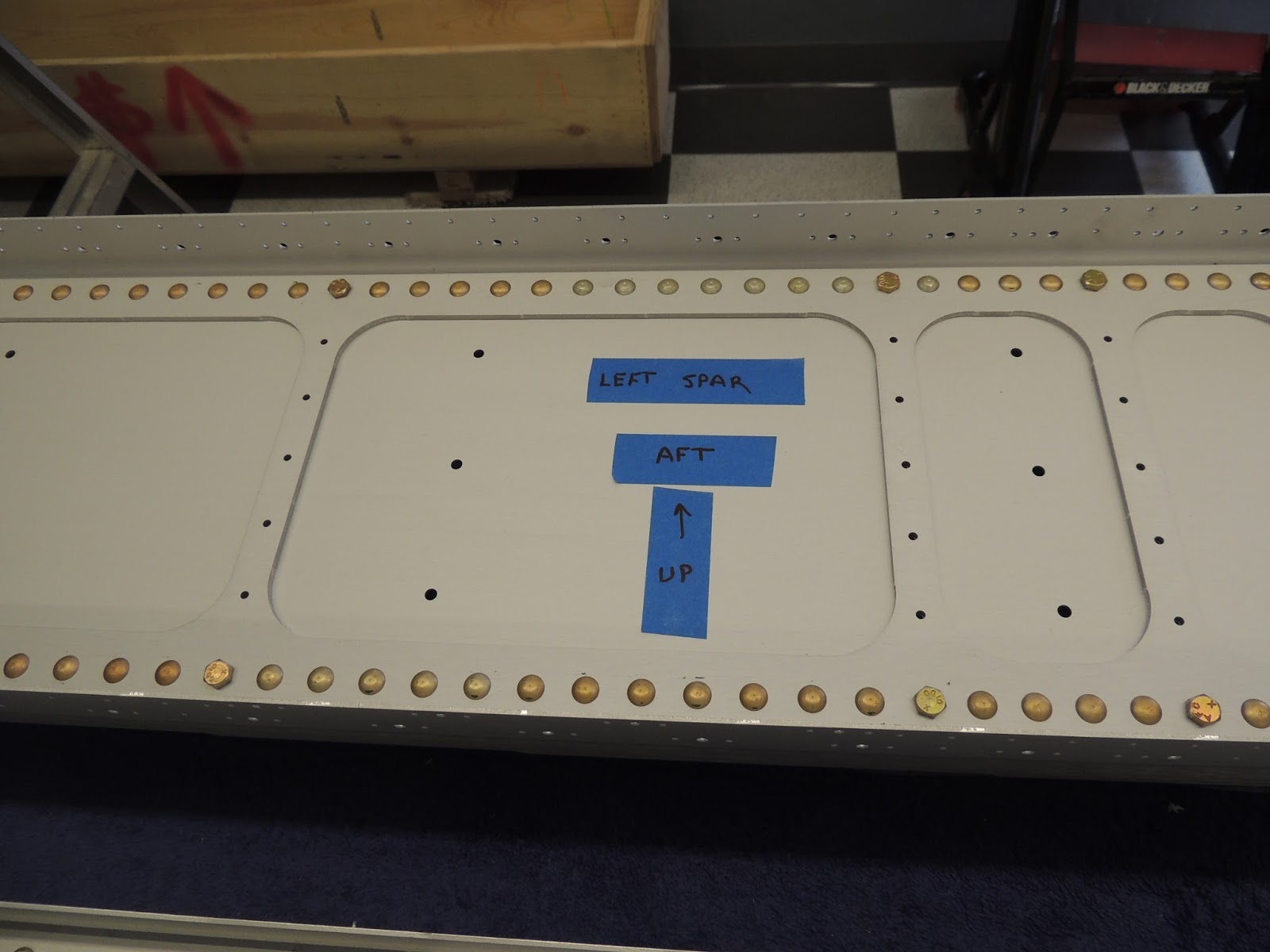
| Here's the left and right wing spars. The spars are very beefy (and heavy)on the inboard portions, but get progressively (less beefy) as you move outboard. The left spar is shown on the right in the picture above with the inboard portion marked with blue tape. The right spar, on the left of the picture, shows what the outboard portion off the spars look like. |
 |
| While it's not too difficult to determine the left/right spar. It's not a bad idea to mark each spar to minimize the possibility of a mistake that could be made at the end of a long day building. The spars are not something you want to make a silly mistake on and have to possibly replace ($$). The wings are essentially built the same and the plans mostly show construction of the left wing unless there is something different between the two. I will be taking my time and reading each step a few times before I move on...especially when it involves removing/cutting/bending metal:) |
 |
The first step when begging work on the main spar section doesn't really involve completing anything on the main spar. There are some J-Channels used later that attach to the upper and lower wing skins. These J-Channels need holes for rivets and the plans have you use the main spar holes (which have the correct spacing that match the skins) to match drill these holes. Seemed kind of risky at first, but actually not a bad idea and pretty efficient. The spar holes have to be final drilled anyway (and countersunk later too), so match drilling the j-channels just prevents a step that would have to be done later. Also, probably easier and more accurate to to use the spar hole to match drill then the other option of using the skins to match drill later. Also, of note in the picture above, is the overlap of the two j-channels. The total combined length required of the two combined j-channels is is roughly 10'. The j-channels come in 6' and 8' pieces. The plans give lengths to cut the j-channels (73 9/32" & 46 1/8"), and designate them as "j-chaanel short" and "j-channel long" once cut. I think I may have made the same mistake as some other builders in the pieces I chose to cut the j-channels. As I mentioned, the kit contains j-chaanels of 8' and 6' lengths. I used the 8' pieces to cut for the "j-channels-long" and the 6' pieces for the "j-channels-short". Turns out (from what I later read from other builders), that only the 8' pieces should be used for this step. Apparently, if you use both the 8' and 6' pieces, you won't have enough j-channel when building the fuel tanks. I have two full 8' pieces left and haven't verified what is needed for the tanks, but it sounds like I may be ordering more j-channel when I start the tanks.
Additionally, because the j-channels will "overlap" to get the full length required, the plans use terms like (nesting in, over, above, under, etc) when describing the overlap area. That was a little confusing..at least for me. The pictures in the plans seem to clarify what they are looking for. However, when you look forward a few sections where the j-channels are actually installed it gets a little confusing again. I just followed the steps and pictures given in this section and just have to trust it is what they are looking for later. The picture above shows the "overlap" I came up with. This is the lower flange of the left spar. The j-channel labeled lower is the "long" j-channel, and extends to the end of the outboard portion of the spar. The j-channel on the left of the picture is the "short" and extends to the end of the inboard portion lower left spar flange.
The channels in this picture "nest" together very nicely. However, I was not able to get a nice nest at all for the upper flange for this left spar. I tried every configuration of j-channel configuration, but nothing worked to get a nice "nest". Interestingly, the opposite was true for the right spar. I got a very nice overlap/nest on the upper spar flange, but the lower had the same issues as the upper from the right. The overlaps on the "problem" j-channels results in approximately .125" difference in flange heights . That, combined with the 1/16" offset required by the plans before match drilling puts the match drilled hole too close to the bend in the j-channel. The plans indicate the flanges for the j-channels may need to be "adjusted" to get a nice fit but, at least in my case, that would require quite a bit of adjusting. I understand the fit is not extremely critical here and we are just wanting to make sure everything matches up later. However, want to explore my options here so, for the moment, I skipped the "problem" j-channel nesting issues until I can come up with a plan.
The following pictures show what I was discussing above regarding the J-Channel overlap/nesting issues I was having. (Update: After spending some time working on my J-Channel issue mentioned above, I found a solution that worked for me. When I cut the j-channels the first time, I just picked up pieces, measured, then cut. I then discovered when I tried to piece them (overlap) together, I had the "nesting" issue. For the replacements (using the long j-channels I had left), I placed the two pieces together along the full length. They all nested nicely. However, as I began sliding the pieces apart the "flange offset" as shown below started to appear. So, to get the pieces that I needed, while also maintaining a good "nesting", I rotated, slid, swapped, etc. the pieces until I was able to get a good overlap at the point where the two pieces met. I then measured the lengths that I need from that nice "overlap" point and made the cuts as required. All overlaps turned out very well. Long story short...don't just pick up pieces of j-channel, measure, and cut.
|
 |
| The picture above shows what I am getting for the Left/Upper and Right/Lower J-Channel transitions. Note the difference of the flanges is about .125". The plans say the bends of the j-channels may need to be adjusted if required to nest tightly. However, I'm not sure I can modify these enough to get where I need to be. When match drilling these, the plans say to raise the flange of the j-channels 1'16" above the spar flange. If I did that for the j-channlels above, the drilled hole would be very close to the bend portion of the j-channel. If I don't raise the 1/16", I may not have the edge distance (or some other clearance issue later) required for the hole to the top of the j-channel flange. Update: See note above regarding my solution to this issue. |
 |
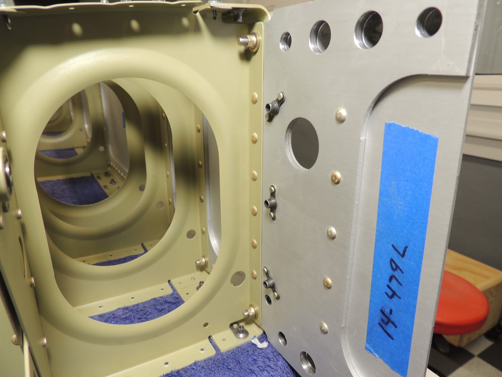
| Here are the same J-Channels as shown above. However, they are positioned as they would be for use as Left/Lower, and Right/Upper. Here the "nesting" is very nice, so I went ahead and match drilled these. I am still working on the transitions for the Left/Upper, and Right/Lower before I match drill those. |
 |
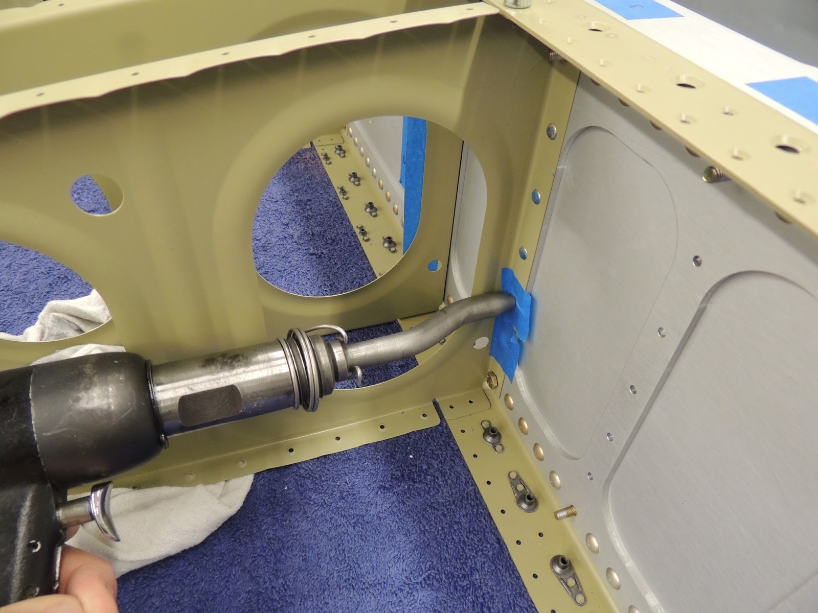
| Here, neighbor Scott and I are match drilling the holes from the lower flange of the left wing spar to the J-Channels that will be used later on when installing the wing skins. |
 |
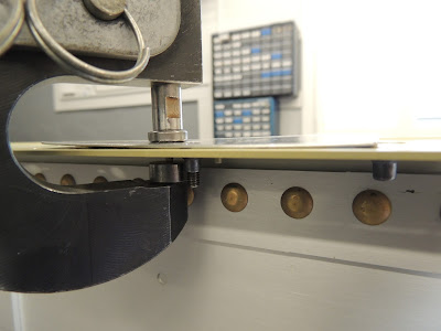
| Per the plans, when match drilling the spar holes to the J-Channels, they want the j-channels above the spar 1/16". We used the rivet gauge to easily check this measurement while drilling. |
January 16, 2017
Like I mentioned above, I was able to solve my j-channel "overlap" issue by trial fitting the j-channels in different configurations before cutting. The picture below shows what I was able to get once I figured out the issue ( I never actually figured out what was going on, I just found a method that worked).
 |
| Here's the J-Channels in place for match drilling on top flange of the left spar. The j-channel to the right (j-channel short) heads to the inboard portion of the spar and, as the plans state, "nests inside" the j-channel to the left (j-channel long), which heads to the outboard portion of the spar. Like mentioned above, I was initially having trouble with the overlap areas for the j-channels on the left spar-top, and the right spar-bottom. This picture shows the j-channel overlap on the left spar-top after solving that issue. There was no "adjusting" or bending required to get this nice fit. |
After several hours, I finished match-drilling the holes (all 524), for the j-channels. Actually not too bad once you get a routine going. This is probably just a warm-up though for what comes next,...all these holes get machine countersunk:)
 |
| J-Channels in place on the left spar after match-drilling completed. |
 |
| Here are the four long and four short j-chaanels after match drilling to the spars. This are used later when installing the left/right wing skins. |
January 21-26, 2017
Welcome to the wonderful world of COUNTERSINKING! :)
There are 586 holes each wing spar (1,172 total) that need to be machine countersunk. So far in my build project, countersinking is one of my least favorite things to do....right up there with de-burring:) I think that's because I have had some past issues where either I countersunk too much and had to replace parts, or didn't do enough and things didn't fit as nicely as I would have liked. Well, after countersinking 1,172 holes, I learned a lot and won't dread it so much in the future. This is only a couple of steps in the plans, however, it does take a LOT of time and it is not something you want to rush and possibly make a silly mistake. Not sure, but replacing a wing spar would probably not be cheap. Not to mention the considerable time required to re-do all that countersinking!
The first holes that get countersunk are for screws that will be used to attach the fuel tanks to the spar (using nutplates), and for screws that will be used to attach wing access cover plates.
I did deviate from the plans a bit here when it came to the countersinking process. I practiced several methods on scrap material before I came up with a plan of attack.
The plans have you install the nutplates first and then countersink the holes. The reasoning here is the nutplates will act as a guide for the pilot of the countersink bit and keep the hole nice and round. Some sort of guide for the pilot is required due to the depth of the countersinking and the thickness of the spar flange. Once the countersink pilot "runs out" of metal, the countersink bit tends to want to wallow around and makes a sloppy hole.
I did quite a bit a of research and it appears most builders seem to agree that Van's method is simple and does work very well in this situation.
However, during my practicing, I discovered a couple of things that I wanted to look at a little more closely. First, because of the metal thickness and the depth of the countersink required, you will end up with a "knife edge" hole. That is expected and the plans give dimensions for the maximum hole size allowed. While the the "knife edge" is expected and allowed in this situation, I really wanted some way to debur the back side of the hole just a tiny bit to take the edge off. With the nut plate installed that would be difficult.
The second thing I was considering was the fact the plans recommend "spot priming" areas where the factory anodized finish is removed due to the countersinking process. With 1,172 holes, that's a lot of spot priming. I though it might be easier to get all the holes countersunk and then lightly prime the whole flange of the spar.
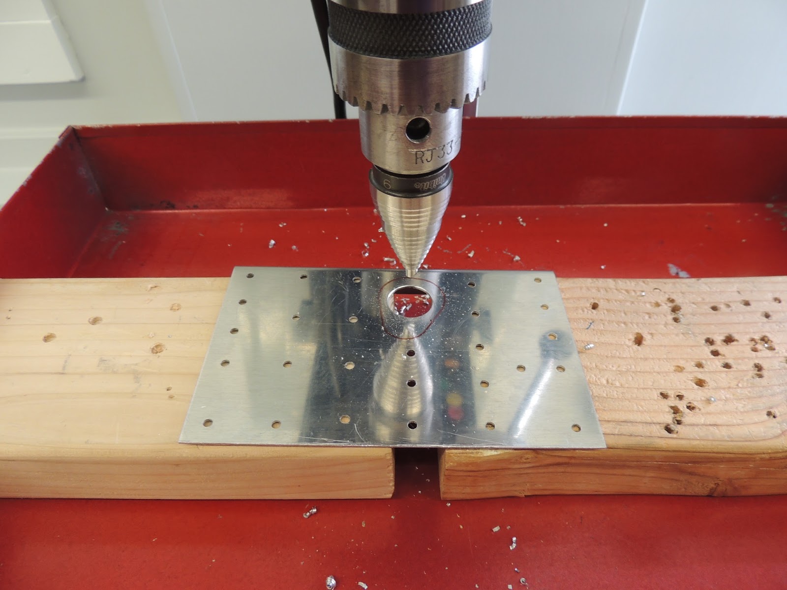
Here's what I ended up doing to countersink the #6 and #8 holes for the wing spar. I actually started with one method and then refined the process a bit about halfway through.
The first method I used was to to make a "jig" from a piece of aluminum angle to act as a guide for the pilot of the countersink bit. I then final drilled the existing holes to #12 so I could use a #12 countersink bit instead of the #30, or #40 (depending on the holes you are countersinking) as called for in the plans. I used a cordless drill at very low RPM when drilling these holes. I also
did not use a countersink cage for these larger holes. I found that if I went slowly until I got the hole close, and then continued VERY slowly, I could watch as each layer of aluminum was removed. I checked for sizing a couple of times as I went using my digital calipers for hole O.D. and properly sized drill bit for hole I.D. This sounds like a very slow and tedious process, but it's actually not too bad once you get the routine down.
The pictures below will show the different methods I used to countersink the hole in the wing spars.
Note: Be very careful when not following the plans in this situation (my process) . There are some holes that get countersunk flush with spar (nutpaltes), and some that get countersunk slightly deeper for dimpled skins. Easy to lose track if you don't follow the plans exactly.
 |
| Here's the materials I used for the first method I started out with for the #8 tank attach holes. The digital calipers are set for .355" I used this to measure the outside diameter of the finished hole. The plans give a max outside diameter for this hole of .370. I found that .355 worked well for me to allow for a nice fit of the .032 skins. I made "test dimples" to check fit. The smaller test dimple worked better as I could get a better feel/visual reference for fit. Also shown are drill bits I used as guides to quickly check for correct and max hole sizing. |
 |
| This is the jig I made to act as a guide for the countersink bit. The two short rivets are used to ensure proper alignment and are just taped in place. The jig is will be held in place using spring clamps during countersinking. |
 |
| View of jig in place on spar flange. |
 |
| Back view of jig on spar flange. The pice of wood is just being used to help the tape hole the rivets in place and help with clamping in position. |
 |
| To help with alignment, I insert a #12 bit while clamping jig in place. |
 |
| Once jig ius in position, I used the #12 countersink bit to enlarge hole to proper size. I used a medium/slow RPM for this initial enlargement. Once I got close, I used a very slow RPM to get the final size required. So slowly, that I could see each revolution remove a layer of aluminum. |
 |
| Her's the hole size that I found worked for me. The plans give a max O.D. hole size here of .370. Here, you can also see the "knife edge" created due to the hole size required and flange thickness. |
 |
| Once the jig is removed, I used this debur bit to remove a VERY small amount of the "knife edge" on the back side of the hole. The plans also give a max inside diameter for this hole. With my deburring process, I did enlarge this inner hole very slightly and came very close to this max diameter. However, I did like the deburred hole much better and I can't believe that removing that extremely thin knife edge piece of material could be a bad thing. |
As I mentioned above, about halfway thought the countersinking of the #6 and #8 holes I refined my process a bit. Pictures below show what I came up with.
 |
| About hallway through (and after sleeping on it) I decide to try and refine my countersinking process for the #6 and #8 spar holes. Basically, instead of using the jig I made, I just used a nutplate to act as a guide for the countersink pilot. I used a K-100-08 (Note: Not the correct nutplate used for final assembly) with the threads drilled drilled out to accommodate the pilot for the #12 countersink bit. |
 |
| Pictures above and below showing my "refined" countersinking process holes for #8 fuel tank attach screws. |
Next, I moved on to countersinking the #6 holes for the wing access plates. I basically used the nutplate process I used for the #8 tank attach screws.
 |
| Here's the materials I used for the #6 wing access plate countersinking. |
 |
| The plans give a max. O.D. for these holes of .308. I found the size shown in the picture worked well for me. |
Once all the #6 and #8 holes were completed, It was time to countersink the remaining holes in the spar flanges. The holes are for the wing skins and are a bit easier (I thought) than the larger #6 and #8 holes. For these smaller countersunk holes, I did convert back to using the microstop gauge.
 |
| Here I'm countersinking the holes for the wing skins. I converted back to using the microscope countersink cage . For these holes, I used a medium/fast drill RPM. From my experience, these countersink cages can be very finicky. One hole will be prefect and next too shallow ( at least never too deep!). I think a good consistent routine helps here. Clean sharp bit, equal "push"pressure, etc. seems to help. |
 |
| I still don't love countersinking..., but I'm getting there:) |
Next up, I will put a light coat of primer on the spar flanges to protect the areas where the factory anodizing was removed during countersinking. Then I will get back to following the plans and start installing nutplates.
February 2-4, 2017
The wing spars come anodized from Vans. The plans recommend priming the areas where the anodizing was removed during countersinking. Because of the large number of holes that were countersunk, I decided to prime the flanges of the spars instead of "touching up" each individual hole.
 |
| Instead of "touching up" the areas of the flanges where the anodize was removed during the countersinking, I decided to prime the entire flange of the wing spars. To prep the spar flanges for priming, I "lightly" scuffed with a maroon scotchbrite pad and dawn dishwashing liquid followed by water rinse. I felt I needed the to remove the residual boelube that was used during countersinking. |
Nutplates:
With the spar flanges primed, it was time to install nutplates for the fuel tank attach screws and wing access panel screws. When installing the nutplates, I used a method that is a little different than normal. I will show what I did in the following pictures.
Note: Remember, I deviated from the plans sequence when countersinking, and installing nutplates so the the following descriptions will not reflect what is shown in the plans.
 |
| When installing the nutplates, I used a method that I tried a few times and it worked pretty well, so I stuck with it for all the spar nutplates. First, I inserted the rivets that will secure the nutplate. |
 |
| I then placed the nutplate on the rivets. I used a small deepwell socket to hold the nutplate in position. |
 |
| With the nutplate in position, I placed a piece of skin dimpled for a #8 screw in position on top of the flange. |
 |
| Here, I have the #8 screw threaded into the nutplate on the underside of the flange. The dimpled skin does a good job of holding the rivets in position while also ensuring the nutplate stays in alignment while squeezing the rivets. |
 |
| Here, I'm using a hand squeezer to set the nutplate rivets. This is the "non-standard" method I mentioned earlier regarding installing the nutplates. Typically, the squeezer dies would be in direct contact with the rivet head. Here, the piece of dimpled skin is between the squeezer die and rivet head. I discovered this method while practicing on scrap and it worked pretty well, so I decide to use it for the spar nutplates. Maybe a little extra effort, but seems to do a nice job in this situation. |
 |
| Here's the top side of the spar flange showing the nutplate attach rivets. |
 |
| This is the tank attach nutplates in position on the underside of the spar flange. |
 |
| This picture shows the nutplates installed on the flanges of the wing spar. |
 |
| This is the aft side of the left spar from around the mid portion looking inboard. The forward row of nutlates are for the tank attach screws while the aft group of four are are for wing inspection plate screws. |
February 5, 2016
It's Super Bowl Sunday (Atlanta Falcons/New England Patriots). I had a few hours after Church and before the game to finish off the few remaining nutplates on the spars. There are four on the spar tip and three at the inboard portion. Some can be squeezed, but but others must be driven with a rivet gun. There are various options to set the the ones that require the rivet gun. I ended up back-riveting. It required a little more set up than just using a bucking bar, but I thought I would get better results.
 |
| These are the nutplates at the tip of the wing spar. The two closest to the tip , the rivets can be set by squeezing. The two further away, I set the rivets by back-riveting. It required a little more setup because I had to "shim up" the whole spar so I could get my back-riveting plate in a good position. |
 |
| Here's the three nutplates at the root of the spar. These are too far in to squeeze, so I back-riveted. Again, I had to shim up the whole spar in order to get the back-riveting plate in the proper position. You can see the back-rivet plate in the picture with the blue tape around its edges. |
 |
| There are five #4 universal (round head rivets) that are also installed at the spar root. These are easily squeezed. Here, neighbor Scott uses the hand squeezer to get his forearm workout:) |
 |
| Before I put the spars away and start on the ribs, there are a few misc. items to complete. Here, I'm attaching the aileron bellcrank brackets to the left wing spar. The AN3 bolts are screwed into pre-installed nutplates that are on the tie-down bracket assembly on the other side of the spar. Also shown in this picture is a new tool I added to the inventory. The torque wrench I will discuss in photo below. |
 |
| I ended up getting a new torque wrench before installing the aileron bellcrank brackets. I was using one of the "clicker" type wrenches before, and was having a tough time getting the proper "click" at the correct torque..especially at the lower torque values. Additionally, this wrench makes it easier to determine the "friction drag" when using the all metal locknuts. There are several online sources for this wrench. I used: Toolsdelivered.com |
February 8, 2017 - Wing Ribs
Wing Rib Prep. Feb 8-13, 2017
As always, before any of the fun stuff can begin (assembly, riveting, etc.), there is some parts prep that needs to be done. There's 14 ribs per wing and each one needs: Flanges adjusted to 90 degrees, deburred, holes final drilled and fluted. This all takes a fair amount of time. I spent at least 20 hours on this process.
The first thing I did to the ribs was to check/adjust the rib flanges to 90 degrees from the rib web. This was called for in the plans, and while this may seem like an insignificant step, I guess it makes a difference as to the final rib/wing skin fit/appearance later on. Most ribs were very close and required little if any adjustment. I researched how to accomplish this flange adjustment and discovered a tool that some builders were using to accomplish this. Luckily, neighbor Scott's dad is proficient in woodworking and volunteered to build this tool for me. He did a great job and it worked perfectly.
 |
| Here's "The Pile" of wing ribs that need prepped before being installed! |
 |
| This is the the tool that Scott's dad built for adjusting ring flanges to 90 degrees. I don't remember exactly where we got the idea/ specs for this, but probably off VAF or an EAA help video. Luckily, most flanges required very little, if any "adjusting", so this step went fairly quickly especially using the tool. |
 |
| Here you can see the angle of the wood block is slightly over 90 degrees to allow for "springback" after bending. |
After flange adjustment, I started the deburring process. I started with all the nooks and crrannies on the ribs. This step took me the longest as it has to be done manually. Although I have seen a few builders come up with some creative ways to do this mechanically, I just went the old fashioned way and used sand paper. For the "nooks and crannies", I used the 3M flexible sandpaper like
this.
 |
| The "Nooks and Cranny" deburring is not very exciting. Here, I did some deburring while on a road trip with the family to Alabama to look at a college for my daughters. It was a 4 hr drive each way and I was able to get 10 ribs completed during the trip! I hope I can cut this 4 hr drive down to a 45 minute flight one of these days...hopefully before they graduate:) |
Another thing I tried this time while deburring was listening to a book on tape. I didn't think I would be a fan of this, but I actually enjoyed it, Definitely, makes the time pass a little quicker. I occasionally found myself wanting to just listen to one more chapter which allowed me to knock out a few more ribs! The book I listened to was"
Unbroken ", by Laura Hillenbrand. Great book!
With the hand deburring complete, I was ready to move on to using some power tools to speed things up a bit.
 |
| Once I finished with the hand deburring of the nooks and crannies, I was able to use some power tools to speed up the process. Here I use the Scotch- Brite wheel to get the edges of the ribs. |
 |
| I used the small Scotch-Brite wheel in the drill press to deburr the lightening holes of the wing ribs. Much faster than hand deburring! |
 |
| The holes in the flanges of the ribs are pre-drilled. However, they are slightly undersized and must be final drilled to #40. I used the drill press and a #40 reamer bit. Didn't use the "press" portion of the drill press. I just moved from hole to hole positioning and drilling as I went. I felt this was much faster than using a hand drill. |
 |
| Next up was fluting. Here you can see the slight"bow" in the rib that is produced during the forming process. For the most part, only the longer, forward portion, of the rib required fluting. The aft portion was pretty straight as is. |
 |
| Here's the rib after fluting. |
 |
| Wing rib prep complete and ready for priming. Finally!:) |
February 18-20, 2017
I thought I was ready to prime the wing ribs, but after reading ahead a bit in the plans, I saw more holes that need to be match/final drilled and also some holes for plastic bushings. I want to get those done before I prime. Nothing overwhelming and it only took a few hours to get it all completed.
 |
| Here I'm match drilling the wing rib to the flap hinge bracket. There are two per wing. The brackets are pretty beefy and the plans say to straighten as necessary. They didn't require much, but what for what was needed I used the procedure from section 5 as seen in picture below. |
 |
| Procedure from section 5 of the pans to straighten thick aluminum parts. |
 |
| One of the flap hinge brackets clecoed in position on the left wing. |
 |
| Here, I have all the wing ribs clecoed in place to the left spar. The forward flanges of the ribs get final drilled and two holes per rib get match drilled for AN3 bolts. |
 |
| Left wing spar and ribs looking outboard. The torque tube support bracket assembly for the aileron is seen here on the most inboard rib. The plans advise that some trimming may be required for this piece to get a good fit with the rib. I found this to be true and had to do a fair amount of trimming/adjusting to get a nice fit. The main issue was getting the holes in the flanges of the rib to align with the holes in the bracket. I've learned from my limited build experience that holes that don't line up nicely now lead to difficult to set rivets later. |
March 2-6, 2017
The wing ribs were finally ready for priming. The priming process (actually spraying the primer) isn't that bad; however, like most parts of this project, there is much prep work required before you get to the fun stuff. I got a late start and only got eight ribs and a few other small items prepped and primed before it got dark. There are 14 ribs per wing. Hopefully will get the rest finished up soon so I can get back to riveting parts together!
 |
| There are two Flap Hinge Brackets per wing. These things are pretty solid and there are several #4 rivets used to keep them in place . I went back to the reliable C-Frame to back-rivet these parts together. |
 |
| These rivets are pretty easy to set (especially using the C-Frame), and it's not too difficult to get some good looking shop heads. |
 |
| Manufactured heads look good too. No smiles here:). Nice to start off with something fairly simple after not using the rivet gun for a few months. |
 |
| The Aileron Torque Tube Support Assembly also gets riveted before the ribs start going in. This piece also goes together very smoothly. I rivet the bearing in first as seen below using the hand squeezer. I then used the C-Frame to rivet the pieces together with the support angle. |
 |
| Here's the finished Aileron Torque Tube Support Assembly. This part will be riveted later to the web portion of the most inboard wing rib (one each wing). The "flags" on the lower portion of the bracket are for molex plugs that are part of the pre-wired harness that comes standard with the RV14 kit. |
March 10-12, 2017
With the wing ribs finally primed, it's time to start riveting them in place on the spar. I labeled the ribs 1-14 during priming with 1 being the most inboard, and 14 the most outboard. Much simpler that way when it comes time to put back in the proper position. Before the riveting begins, there are several AN3 bolts that need installed. They are all different lengths and sometimes oriented in different directions. It can be a little confusing and the page in the plans thats shows this is is very "busy". I had to refer that page several times to make sure everything was installed properly.
Additionally, these bolts came preinstalled in the spars and had to be removed to use again during rib installation. Some builders replace these bolts with new hardware, and I considered doing the same. The locking nuts used here are the all metal version with a "distorted" hole, that provides the locking feature. Because these nuts and bolts were previously used on the spar, they do show a very slight amount of wear and may not have the same locking value as when unused. The bolts look fine except for being a little shiny on the threads where the nuts wore off some of the factory coating. After a fair amount of research I decided to keep the bolts and reuse; However, I did use all new locking nuts.
 |
| Left wing ribs in place ready to be riveted to the spar. |
 |
| Here's one of the AN3 bolts used to attach the ribs to the spar. These bolts/nuts come pre-installed on the spar and are removed and are re-used when attaching the ribs. As discussed above, some builders replace with new hardware due to possible wear on the "used" parts. After considering doing the same, I elected to only replace the all metal lock nuts. As seen in the picture, the bolts do show that some factory coating was removed due to the previously installed metal locknuts; however, the threads remained in good condition. |
 |
| The bolt orientation diagram on the plans can be a little confusing at first. However, after staring at it for awhile like you stare at on of those pictures where the stars all appear 3D, it all of a sudden becomes clear:) Here, you can see that the top and bottom bolts are oriented in different directions. |
 |
| When riveting the wing ribs, we used the offset rivet set and a tungsten bucking bar. This job could be done solo, but definitely easier with as partner. (UPDATE: See Revision 3 below for my preferred method to rivet the ribs) |
 |
This is the offset rivet set we used for the left wing ribs. Definitely need to be carful using this set as it has a tendency to turn during use and increase the chance to come off the rivet head and cause a "smiley". Since I had a partner, I was able to use both hands and stabilize the set. If solo, I've seen some builders use tape to keep the set from turning.
Update: (SEE Revision 3 below for preferred method to rivet the ribs) I've seen on some builders sites that it is possible to use a longer straight set and just move the ribs slightly to set these rivets. I have a couple more ribs on the left wing to rivet, so I will give that method a try and post the results. |
March 20-22, 2017
I had a couple more left ribs to rivet to the spar so I decide to try the straight rivet set like I had seen some other builders use instead of the offset set I had been using. I like the straight set much better. We were able to use a lower air pressure and still set the rivet in a shorter time than with the offset.
Once the left ribs were completed, I moved on to prepping the parts for the rear spar. As usual, there is a fair amount of "behind the scenes" work that takes place before assembly can begin. In this case; in addition to some match drilling and a small amount of machine countersinking,there are four (two each wing) aileron hinge brackets that need to be assembled. The two inboard aileron brackets are part of a service bulletin that were included with my wing kit to replace the original brackets.
 |
| Like I mentioned above, I set the rivets for the majority of the left wing ribs using an off-set rivet set. I saw some other builders had used a straight set for the ribs so I decided to give that a try for the last couple of ribs on the left spar. I looked through the bucket of borrowed miscellaneous sets I had from friend Mark and luckily, I found the perfect one. He had even ground down one side of the set to make it even fit better for this situation. As seen in the picture, because the aft end of the rib is not attached to the aft spar yet, you can move the rib slightly out of the wt to get a straight shot on the rivet. We were able to use less pressure and set the rivet in much fewer hits than when using the off-set set. This method worked very well, and I will definitely be using this for the right wing ribs. Overall a much smoother way of setting these rivets. Update: (SEE Revision 3 below for preferred method to rivet the ribs) |
 |
| Here you can see how Mark had ground down the tip of this straight set. There is a raised "lip" around the rib lightening hole and this flattened area allows for a nice flush fit on the rivet head. Update: (SEE Revision 3 below for preferred method to rivet the ribs) |
 |
| The length of the straight set used for the ribs is also important. This length worked well as it put the body of the rivet gun in the area of the second rib lightening hole. Update: (SEE Revision 3 below for preferred method to rivet the ribs) |
REVISION 3 of rib to spar rivet technique.
I mentioned above that I started with the offset rivet set when setting the rivets for the ribs to spar. I wasn't completely happy wit the results due to what seem like an excessive amount of "drive time" when setting the rivet. From what I've learned now, the extra pressure/drive time required is common du to the offset set. I later moved on to the straight set with the tip filed flat on one side and it worked much better. However, when I set the rivets for the ribs to spar for the right wing I used yet another technique and that its now my preferred method (if I ever build gain:). My new preferred method is a straight set as I used before. However, it is slightly longer which easily allows the rib to be moved out of the way so you can get a nice square fit on the rivet head. It required less pressure, a shorter set time, and seemed more controllable. All rivets turn out very nice.
 |
| This is revision 3 of my wing ribs to spar riveting technique. I used this on the right wing. This longer set allows the ribs to be moved slightly out of the way allowing a nice square fit on the rivet head. |
 |
| Here, you can see the rib move slightly to allow a nice straight shot at the rivet. This technique worked much better than the two previous methods I used on the left wing. |
One thing I will also mention is something I did a little differently than shown in the plans. There is a Torque Tube Bracket Assembly, that is attached to the most inboard wing rib. The plans have you rivet this assembly to the rib before the rib gets riveted to the spar. I noticed that if this is done, the rivets that attach the rib flange to the spar would have to have the shop head on the rib side due to clearance issues because of the already attached Torque Tube Bracket on the rib. I'm sure there is no issue at all with having those rivets with that orientation, but because I had all the other ribs set with the shop heads on the spar side, I wanted to see if I could keep that consistent. After consideration, I decided to hold off on attaching the Torque Tube Bracket to the rib until
after I had riveted the rib to the spar. By doing this, you are pretty much limited to bucking the rivets that attach the Torque Tube Bracket to the rib with a gun and bucking bar. This also requires the manufactured heads of the rivets to be on the bracket side of the assembly instead of the rib side. Typically, it is preferred to have the manufactured rivet head on the thinner material, which in the case is the rib. However, the part thicknesses here are very close, and considering all the other factors when setting these rivets, I decided it probably wasn't a factor. I think this method worked out well for me and I ended up with a nice secure assembly. As always though, study all variables for your particular situation and make a decision accordingly.
 |
| Here's what I discussed above regarding attaching the most inboard wing rib to the spar. I decided to set these rivets with the manufactured heads on the rib flange side. I order to do this, I had to hold off on mounting the Torque Tube Assembly Bracket to this rib until these rivets were set. As mentioned above, this is different than shown in the plans. |
 |
| This is the Torque Tube Support Bracket that is attached to the most inboard wing ribs. Again, I did this in a different order than called for in the plans. I attached this after, riveting the rib to the spar. See discussion above. |
 |
| To set the rivets (all but one) on the Torque Tube Bracket, I once again used the straight set that is ground flat on one side. This allowed a nice flush fit on the universal head of the rivet. There was one rivet where I had to use the offset set because of a clearance issue caused by the bearing mounted on the bracket. |
 |
| Setting the rivets that attach the Torque Tube Bracket to the most inboard wing rib. |
 |
| Torque Tube Support Bracket Assembly attached to the left wing rib. |
 |
| Shop head of rivets on the rib side of the Torque Tube Support Bracket Assembly. |
With the left wing ribs riveted in place to the the spar, I moved on to prepping components for the rear spar of the left wing.
I began with assembling the left and right Aileron Hinge Brackets. There is a service bulletin out for the existing brackets and this is the replacement parts. Luckily, I had not installed these parts prior to the service bulletin being issued, otherwise I would have to remove and replace with the new parts.
 |
| This piece of pre-drilled angle is what is used to mount the new brackets to the rear spar. This piece gets separated into four pieces. NOTE: I saw a post on VAF where a builder stated that after installing the new SB hinge brackets that there was some rubbing of the aileron wing skins and the round heads of some of the rivets used to secure this piece. There was a couple of solutions to this rubbing. One involved using flush rivets on three of the holes. Be aware that if you switch to flush rivets, edge distance is close on one of the rivets, and you need to plan accordingly when cutting this piece of angle. More info below. |
 |
| Here's the pieces after cutting. Not real obvious in picture, but I allowed as much edge distant as possible for the lower rivets on each of the longer pieces. They don't give you much extra space, but I cut straight on one flange of the angle and then at a slight angle on the other flange where I needed the edge distance. |
 |
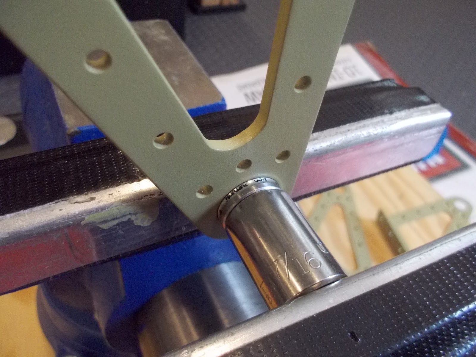
| Here's the service bulletin aileron bracket (left) after some prep work. |
 |
| Another view of the left aileron hinge bracket. |
 |
In this picture, you can see the holes I decided to countersink to alleviate rubbing the aileron wing skin issue I mentioned above. I checked with Vans, and they said this is probably not a bad idea given my stage of the build. The holes I am referring to are the four holes on the piece of angle that attaches to the hinge assembly.
Note: As seen in picture, I countersunk four of the holes. After doing more research, if I had to do it again, I think I would only countersink the lower three. No structural issue with the way I did it, but when you look at how the pieces of this part are assembled, you will see the top two rivets go through two pieces of material instead of three like the lower three holes. I think it would just "look better" if the top two rivets were the same. |
 |
| This picture shows the Aileron Hinge Bracket assemblies for the left wing. The one on the right is the inboard (service bulletin part), and the outboard bracket is on the left. |
 |
| This is a doubler plate that is used on the rear wing spar. It is used to beef up the area where the aileron hinge bracket attaches to the rear spar. There is a pre-cut hole in the rear spar for the aileron push-rod and that hole needs to be transferred to this doubler plate. I really didn't have a plan on how I was going to cut this hole other than get started with a unibit and go from there. Here, I'm drilling a pilot hole for the unibit. |
 |
| Opened the ole up with this unibit. |
 |
| After cutting the hole in the doubler with the unibit, I still wasn't sure how I was going to enlarge it. After trying a few ideas, I found this attachment in my dremel kit. Wasn't sure if it was made for metal, but it worked great. |
 |
| After getting the hole close with the cutting tool, I switched to this dremel sanding attachment that I chucked in my drill press. |
 |
| Getting close. |
 |
| Next, I clecoed the doubler plate that I cut the hole in to the rear spar to match the holes exactly . |
 |
| Here's the left rear spar clecoed in place to the wing assembly. There is some drilling and a small amount of machine countersinking required before I can debur and prime. |
March 23-24, 2017
After drilling and countersinking the left rear spar, I decided to delay the deburring and priming due to a couple of rainy days. Instead, I decide to finish final assembly of the inner and outer Aileron Hinge Brackets. I can use my air brush indoors to prime the pieces, so weather is not a factor.
 |
| Here I'm using the airbrush to prime the Aileron hinge brackets. The air brush only needs about 15-20 psi air pressure and produces very little overspray and fumes so I occasionally use this to prime small parts indoors (with doors open)when the wx outside does not cooperate. However, because of the narrow spray pattern and low volume, I find this procedure only practical on smaller parts. |
 |
| To set the rivets on the aileron hinge brackets, I used the hand squeezer. Where possible, I held the pieces together with a vice during riveting to ensure a tight fit. |
 |
| Here's the completed left and right (service bulletin) inboard aileron hinge brackets. |
 |
| Here's the parts for one of two outboard aileron hinge brackets. The bearing must be pressed into the middle piece of the bracket. |
 |
| Prior to pressing the bearing using the vice as described in the plans, I use finger pressure to make sure the bearing is aligned properly with the hole in the bracket. |
 |
| For the initial press of the bearing, I place the socket on one side of the bearing.. |
 |
| After the initial press was complete, I then placed the larger sized socket on the back side of the bracket to complete setting the bearing. The bearing sticks out just a bit on each side of the bracket when properly set to fit the recessed portions of the exterior parts of the bracket. |
 |
| Bearing in place after pressing into center piece of aileron hinge bracket. |
 |
| The completed aileron hinge brackets for the left wing. The bracket on left is the exterior and will be mounted on the aft wing spar near the wing tip. The inboard bracket on the right will be mounted to the rear spar about mid wing. |
April 7-13, 2017
I continued prepping the left wing rear spar and associated parts for final assembly. This included a small amount of machine countersinking, match/final drilling doubler plates, and,of course, debur and priming.
Once all the parts are ready for assembly, they are attached to the rear spar prior to the rear spar getting attached to the wing ribs. I spent a fair amount of time trial fitting all the pieces trying to develop a plan for riveting. One thing in particular that I spent some time on was rivet orientation.
Where possible, I wanted to follow the standard practice of orienting the rivet so the manufactured (round) head of the universal head rivets were on the thicker material. There are two fairly thick reinforcement doubler plates located on the inboard section of the rear spar. These two doubles are much thicker than the rear spar material and I really wanted to place the shop heads of the rivets on these thick doubler plates. The plans don't specify rivet direction in this case so typically it is left up to the builder to make an educated choice. Some factors might include; clearance issues, to include being able to set the rivet properly, also possible interference with other moving parts, possible rivet removal if required, and maybe event aesthetics.
In the case of the two doubler plates, I did notice a possible clearance issue with six rivets if I put the shop heads on the doubler plate side. These six rivets are used to attach the top skin to rear spar flange. It is tight in this location because the thickness of the two doubler plates will make it difficult to get a bucking bar or squeezer on the shop heads of these rivets. It will be a tight fit no matter what side of the rivet is placed here. It appears, after looking at other builder blogs, that most opt for placing the round head on the doubler side. I'm sure this is acceptable and maybe the best choice here. However, I had in my head that I wanted the shop heads on the doubler. So, after some trial fitting and considering my options for setting these rivets later, I decided to go for it. Shop heads on the doubler it is. I'll deal with those six rivets when the time comes:)
Rivet orientation for the rest of the rear spar was pretty standard, and for the most part, I will place the rounds heads on the aft side of the spar. However, I did consider briefly placing the rivet shop heads for the aileron brackets on the aft side. This would definitely follow the standard practice of placing the shop head on the thicker material, however, after considering some of the other factors I discussed above, I opted to place the universal heads on the raft side here too.
 |
| Here's the rear spar for the left wing with all the associated parts clecoed in place to the wing ribs. |
 |
| Here's the doubler plates I discussed above on the inboard section of the rear spar. This is the location of the six rivets that will be difficult to set later on. They are on the top flange of the rear spar where the skin attaches. This is due to the thicknesses of the two doubler plates and rivets used to attach them creating clearance issues for squeezer or bucking bars when setting these rivets. In the picture, I have a universal head rivet temporarily in place just to check clearance issues. |
 |
| Another view of the possible clearance issue discussed above. I just have the universal head rivet temporarily in place to check clearances. I have the skin temporarily in place here as well. |
 |
| I think this may be the bucking bar that may have to use later to set the six rivets discussed above. Also, as discussed above, I ultimately decide to place the shop heads on the aft side of this doubler instead of the manufactured head as shown in this picture. I did simulate that situation as well and it appears to have about the same clearance issues. I will cross that bridge when I get to it. |
 |
| I used a hand squeezer to set the rivets for the rear spar reinforcement doubler plates. Here you can see my final decision to put the shop heads on the doubler plate side. The rear spar is not attached to the wing ribs at this point. I just had it clecoed in position for stability, and also as a visual reference to what was going on. However, because I had it clecoed in place, I had to use two different squeezer heads to set the rivets. For the top row, I used the head as seen in this picture. The bottom row, I had to use the longeron yoke in order to clear the spar flange. Probably doesn't matter, but I started at the center of the doubler and worked my way out also alternating top and bottom as I went. I did have two squeezers set up with the different heads to speeds things up slightly. I have a borrowed pneumatic squeezer and it would probably work great hear, but once I got started with hand squeezers, I just kept going. |
 |
| This is the squeezer head I used for the lower row of rivets on the aft-spar doubler. As seen in the picture below, the bottom flange of the spar faces forward. If I didn't have the spar clecoed in place, I could have just flipped the spar over and used the normal squeezer head. However, I did have two squeezers set up, so this worked ok for me. |
 |
| The rear spar reinforcement doubler plates riveted in place. The clecos are located where rivets are placed later to attach the rear spar to the wing ribs. |
 |
| Forward side of the rear wing spar showing the universal heads of the rivets that were used to attach the doublers on the aft side. |
 |
| This is the inboard aileron attach bracket for the left wing. As discussed above, I put some thought into the rivet orientation I wanted to use here. I initially preferred placing the shop heads on the aft side, but ultimately decided to place the universal heads aft on the bracket flanges. Setting the rivets for this bracket I used a combination of rivet gun and squeezer. On the right side of the bracket, because of clearance issues with previously installed rivets, I used the rivet gun and bucking bar. The "modified" rivet set I used was the one I have borrowed from friend Mark. It's the same one I used on the wing rib to spar rivets. This "modified" set allows a nice flush fit on the universal head of the rivet. |
 |
| Setting the rivets on the other side of the aileron bracket, I was able to squeeze all but one. This was due to the fact that I had countersunk the rivets (see discussion above) used to attach the angle brackets to the aileron hinge. This allowed room for the squeezer head. I had to set the top rivet with a rivet gun and bucking bar because I did not countersink the rivet in that location that attaches the angle bracket to the aileron assembly. |
 |
| The next few pictures just show the completed riveting for the inboard aileron bracket for the left wing. |
 |
| Forward side of the aft wing spar where the aileron bracket attaches. As a reminder, this is a service bulletin replacement aileron hinge assembly. I was lucky that I had not installed original equipment prior to the service bulletin being issued and did not have to "remove and replace". |
 |
| View looking down on left aileron bracket assembly. |
April 16, 2017
After completing the riveting for the parts to the wing rear-spar, it was time to attach the spar to the wing assembly. I put some thought into the ways I wanted to set these rives rivets and also the orientation of the rivets. I came up with a plan that may seem a little inconsistent as far as aesthetics, but in the end, I think it will look fine. For the most part, except for the spar doubler, I placed the manufactured rivet heads on the aft side of the spar. Where ribs attach to the spar, the shop heads will be on the aft side of the spar. Later, a flap gap fairing will "hide" all but the last two bottom rows of rivets. I plan to continue with the manufactured heads on the rib side when it comes time to attach this fairing, but will place the manufactured heads on the aft side along the gap fairing in all other holes along the aft spar. Sounds confusing and busy, but I think it will turn out ok.
 |
| Setting rivets that attach the wing rear spar to the wing ribs. I used hand squeezer with the yoke shown in picture for top two rivets, and the longeron yoke for the bottom rivets. After some thought, I decided to put the manufactured heads on the rib flange side. From prior experience setting rivets on ribs, I've had much better luck getting a nice tight fit doing it that way. Additionally, this also follows the practice of placing the manufacture head on the thinner material. |
 |
Squeezing the rivets for the rib to spar connection. I placed the manufactured heads on the rib flange side.
|
 |
| Showing the manufactured heads of the rivets on the rib flange side. The rivets in this particular location were a little more difficult to set due to previously installed rivets that attach the flap hinge bracket. There are two ribs like this on the rear spar. I ended up finding a small reduced diameter "cupped side" set for the # 4 rivet. I then used washers on the "shank" of that set to space the "cupped" set out as required to clear the existing rivets. It worked out great. Wish I would have taken a picture so it would be a little more clear. The other ribs that don't have the flap hinge bracket are easily accessible with the normal sets and are easily squeezed. |
 |
This is the inboard section of the wing rear spar. The holes that don't have rivets are for later installation of the flap gap fairing. Additionally, you can see the shop heads on the lower row. This is due to the manufactured heads on the aft side are countersunk.
|
 |
| Aft view of the shop heads on the spar doubler. The empty hole are for the flap gap fairing installed later. |
 |
| The lower two rows of rivets that correspond to the doubler on the aft side of the spar are countersunk on the aft side. In these locations, the shop head has to be placed one the flange of the ribs. |
 |
| I used the "washer trick" to ensure a nice tight fit was maintained while squeezing these rivets. I believe these are some type of faucet washers. There are a several different types available. The was needed for this are the soft/flexible type. Update: I am having trouble finding the soft rubber type washers. In the plumbing section I and only finding the hard rubber type. I will have to look around some more, or convert to rubber "aquarium" hose cut to required length like I have seen a few other builders use. |
 |
Enough washers are placed on the rivet shank so that the washers are protrude further out than the rivet shank. This will allow the squeezer set to compress the washers before contacting the rivet shank thus squeezing the parts tight before the rivet starts to set.
|
 |
| When using the "rubber washer trick", you set the rivet just enough to swell it slightly and hold the parts together. The washers are then roomed and the rivet squeezed normally. |
April 18, 2017
 |
With the wing rear spar attach complete, it's time to move on to the top wing skins.
|
 |
| These are the wing walk doubler skins. Sandwiched between the four inboard ribs and the top inboard wing skin, they provide extra strength in the area where you walk on the wing to enter/exit the airplane. Make sure the forward edge of the forward doubler is not overlapping the spar flange. I would imagine that may prevent the top skins from fitting flush on the spar flange and prevent a smooth fit between the tank skins later on. Mine overlapped very slightly and needed filed down a bit. |
 |
| The top-inboard wing skins are placed over the wing walk doubler skins. Because of the doubler plates underneath the inboard portion of these skins, the skin to rib rivet holes cannot be dimpled and have to be machine countersunk. Since the wing skins in this location are .032" thick, you have to be careful to not "over" countersink these holes. |
 |
| Here's one of the rivet holes in the inboard wing skin that gets machine countersunk. Because of the skin thickness, the plans advise to be careful to not countersink these holes too deep. The plans even state that it would be preferable to have the countersink up to .005" too shallow. When the plane is complete, there will be non-skid placed in this area, so the slightly proud rivet heads should not be visible. The rivet in the picture is not set, and just shows the average depth of what I was shooting for in this area. I did use the countersink cage for theses holes, bur it is still difficult to get every hole countersunk exactly the same. I would use the countersink cage to get the hole close to the depth I was looking for and then use a hole debur bit turned by hand to fine tune the final depth. |
 |
| Here's the four rows of rivet lines on the inboard top wing skin that get machine countersunk. There are also some holes on the inboard most rib line that get match drilled for nutplates. |
April 26, 2017
 |
| The two top wing skins overlap each on the approximately 1/3 in from the inboard edge. The outboard skin overlaps the inboard. To help reduce the visible increase in thickness in this overlap area, the plans advise to reduce the thickness of the two skins at the leading edge corners. The top of the inboard skin and the bottom of the outboard. This is kind of a "calibrated eyeball" exercise. I used a file to get things going then switched to various grits of sand paper to finish it off. This procedure requires a few trail fits of the skins in between filing and sanding to get the skins ton the thickness you are after. |
 |
| Getting close. |
 |
| This is what I ended up for the area where the skins overlap. The fuel tank skins that will later be placed just forward of these skins are .032" thick. The plans say to use a scrap piece of .032" aluminum to check for fit/finish. |
April 27-30, 2017
Priming and Dimpling. The weather was nice the last couple of days, so I took the opportunity to catch up on some priming. It pretty much turns into an all day event by the time I prep the parts, let them dry and then prime. Definitely not my favorite thing to do, but the more I do it the less painful it seems to be. I think I'm just getting the routine down better and know what it takes to get er done.
 |
| This is the outboard top wing skin getting the holes dimpled for flush rivets using the DRDT-2. A little time consuming but, actually not a bad process at all. I took the opportunity to start a new book on tape. This time it's Flags of Our Fathers by James Bradley. I started listening to the books on tape when I was in never-ending rib deburring phase. It seems to help with the monotony of some of the less exciting airplane building tasks. |
When I finished dimpling the top skins. It was time to place the wing assembly in a position so that the skin can be riveted to the ribs. I've seen several methods for accomplishing this from other builders sites. Some go ahead and build a wing stand ( that will be very handy to have later on anyway), and use that to support the assembly while riveting the skins. However, the plans method just has the assembly placed on a bench with spar side down and supported accorded accordingly. I opted for the plans version mainly because I didn't want to stop progress to do the carpentry work required to build the stands. I will put that off for another day. I also like the plans version because I felt that I would be able to better support the whole spar assembly and keep everything straight and square during riveting. The spar actually has a fair amount of "flex" in the fore/aft plane until the skins are riveted in place. Because of this "flex", when the spar is placed "face down" on the work bench, there is a bit of sag, and possibly twist, in the middle portion. To alleviate this, the middle areas must be supported/shimmed to keep everything nice and straight.
 |
| Here, the left wing assembly is placed in position on the bench so the skins can be attached and riveted. I decided to wait and cleo the skins in place after I got the spar and rib assembly supported and everything was nice and square. I think it worked out well. However, one small item was that I did have to remove the skin doublers that are shown in this picture and replace them as I was "hanging" the inboard skin. |
 |
These pictures show how I supported/secured the inboard and outboard portions of the spar. I tried to get the inboard end as level as possible and then match that throughout the length of the spar. The pictures below show how I secured the outboard portion of the spar. Because there is a rib on the most outboard portion, it is difficult to secure this end. I really wasn't looking to clamp this end very tight because I was worried about inducing some twist. I just wanted to lightly secure somehow so it would stay in place while attaching skins and riveting. I ended up using an existing hole in the spar (had to remove a plastic bushing) to "sandwich" the spar between two pieces of plywood using a wood screw through the hole. I then clamped the lower piece of plywood to the work table.
 |
| Like I mentioned above, the spar does flex a bit while placed in this position until the skins are attached. It must be supported/shimmed to keep it straight and square. The twist is fairly easy to keep and eye on using a level at several locations down the length of the spar. |
|
 |
| I mentioned in the earlier picture caption the twist is easy to check using a level across the spar flanges. However, to check for sag down the length of the spar is was little more difficult. There is probably a great way to check this, but it just wasn't coming to me. I tried a few things: I put clecos in the spar holes along the length and rested the longest straight edge I had on the clecos, I also rested the straight edge on the bench and just "eyeballed" the top of the straightedge and the spar holes, and finally, I used a string attached at each end of the spar to check for alignment with the spar holes. Between all the methods, I felt I came up with the spar as close to straight as I could get it. |
 |
| Here's the string at the mid portion of the spar. More shimming required here to get a little more straight. Even with the string very tight, there is a small amount of sag in the string that needs to be accounted for with a calibrated eyeball. |
 |
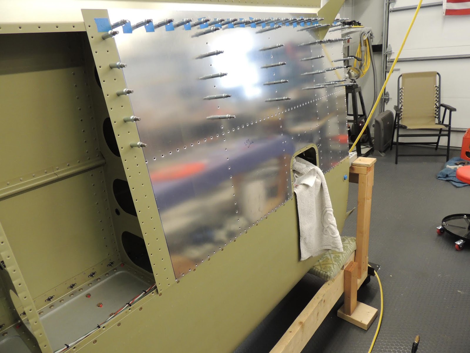
| Top wing skins clecoed in place on left wing assembly prior to riveting. |
 |
| Bottom of left wing assembly. |
 |
| Luckily, neighbor Scott was available to help with riveting the wing skins. Some of these rivets can probably be done solo (many builders have done it), although it is very nice to have a partner for this. As seen in the picture, we decided on using the bucking bar on the shop head and rivet gun with mushroom set on skin side. We debated and practice before making that decision. Vans, and many builders, recommends using back-riveting when attaching skins to ensure a nicely set rivet and smooth skin finish. However, I have just never had good results with back-riveting skins using the long back-rivet set required here. My shop heads just don't turn out as nice as I would like. I'm sure it may produce great result for those that have it figured out, however, I just haven't broken the code yet. |
 |
| Scott and I riveting the skins. Here, I'm making the rivet gun and Scott is on the bucking bar. |
 |
| Here's the rivet set combo we used for the skins. The tungsten bucking bar has a slight angled end that works nicely to offset the bucking bar a bit from the rib when setting the rivet. As I mentioned before, there are various options for setting these skin rivets. This worked for me, and while I believe the skin finish turn out pretty well, it is probably not the level finish you may get using back-rivet set and large bucking bar. Your experience may vary. |
May 6-11, 2017
 |
| Scott and I continue riveting the top skins for the left wing. Just a note here..I believe we "upsized" the rivets along the aft spar line to one size longer than the plans called for. These are fairly easy to set and we had no issues getting a good shop head. We may have found a few other locations as well where we "upsized" the rivets from the plans callouts. It just depended on location and whether or not we felt we could set the rivet and achieve a nice shop head. |
 |
| I discussed these five rivets earlier when I was setting the #4 rivets that attach the doubler to the rear spar. I knew these five rivets would be interesting to set, especially since I put the shop heads of the #4 rivets on the aft side. I don't regret that decision, however it does make setting these five rivets slightly more difficult. |
 |
| Here's the bucking bar I used to set the five rivets discussed in the previous picture. Pretty tight quarters here and I definitely didn't want to damage the spar doubler of the shop heads of the #4 rivets already in place. |
 |
| The rivets set ok and I am glad it worked out. I thought that I may have to use blind rivets of some type for a couple of these five rivets, but everything worked out well. I mentioned above, that we "upsized" the rivets in the aft spar line to -4 lengths I believe. However, due to the tight spacing for these five rivets, we stuck with the plans callouts for a -3.5 rivet length. |
There's a couple of things I've been working on before I move the left wing assembly off the workbench and move on to the right wing. One is determining my "pitot tube plan" for the left wing and the other is mounting the outboard aileron bracket. I finally decided on my "pitot tube plan" and I will discuss/show pictures later. The other final item that needed finished was installing the left outboard aileron bracket. With these complete, I will move on the to right wing and bring it to the same level of "completeness" as the left.
 |
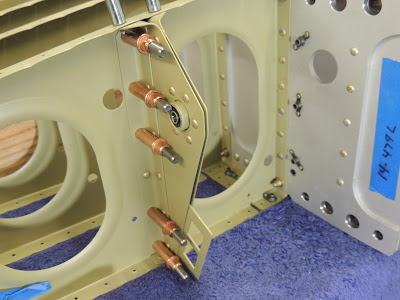
| This is the outboard aileron bracket for the left wing. I was able to squeeze all the rivets for this bracket. However, I did have to use a variety of squeezer yokes ands configuration due to limited acres of a couple of the rivets. |
 |
| I squeezed the rivets that attach the bracket to the most outboard wing rib first. I used a "stubby" yoke thru a rib lightening hole to set these rivets. |
 |
| Along with the "stubby" yoke mentioned above, I also used a reduced diameter set due to limited access to the universal head of the rivet. Also seen in this picture are some washers I used as spacers to give even more clearance. The washers were only required to set one of the rivets. It was the lower rivet located in the corner of the rib and rear spar. |
 |
| This shows the difference in diameter of the two 1/8" rivet sets. The reduced diameter on the right is what I needed to access the rivets mentioned in the pics above. |
 |
| Manufactured heads for the rivets that attach the outboard aileron bracket to the outboard wing rib. |
 |
| Shop heads for the rivets that attach the outboard aileron bracket to the outboard wing rib. |
 |
| Next, the aileron bracket is riveted to the aft spar. I used a combination of squeezer yokes to set these rivets. Here, the longeron yoke is used. |
 |
| My longeron yoke would not reach the two upper rivets of the aileron bracket. I almost resorted to the rivet gun and bucking bar. However, after rummaging through my borrowed collection of yokes from builder friend Mark, I found this yoke with a longer reach. |
 |
| Shop heads of rivets that attach aileron bracket to rear spar. |
 |
| Manufactured heads of rivets that attach aileron bracket to rear spar. |
October 1, 2017
I haven't posted an update in a while as progress over the summer was slow. I had several projects around the house that just kept coming up. As the saying goes, "Sometimes life gets in the way", and I guess that's a good thing!
Anyway, I did manage to bring the right wing to the same level of "completeness" (spars,ribs, top skins, etc.), as the left wing. I didn't post any pictures because the assembly process of the right wing was the same as the left. It did go a little faster than the left wing because I didn't have to figure out the logistics (rivet setting, rivet orientation, squeezing/bucking options, etc.) of my assembly plan. Additionally, as with the left wing, I was lucky that neighbor Scott was available to help when an extra hand/brain was needed.
 |
| Completed sections of left/right wings. Stored on the floor for now until the leading edges are constructed and attached. I will then need to resort to woodworking and construct a wing rack. Luckily, there are many examples and plans available from builders that have gone before me. |
January 8, 2018
Over the last few months, we've been continuing work on sub-structures (leading edges, landing lights, etc.) that will be added to the primary wing structure. The picture below shows progress up to this point. Top wing skins are on, leading edges are attached, and landing lights are installed. The bottom skins are clecoed in place, but will not be riveted until later. At this point, the next step in the plans is to begin building the fuel tanks. For the non-builders, the fuel tanks are basically another wing leading edge section that will be mounted inboard of the previously installed outboard leading edge section. In the photo below, the fuel tank will be located in the vacant area in the lower right part of the primary wing structure.
Wings moved to wing cradle as seen in photo below. For information on wing cradle construction go to miscellaneous section on front page of blog, or click - Wing Cradle Link
 |
| Left and right primary wing structures in cradles. Top skins riveted in place, leading edges attached, and landing lights installed. The lower skins (covered in blue plastic here), are just clecoed in place and will be riveted once the fuel tanks are installed and a few other wing interior items are completed. |
February 2019
Returned to the wings to finish up a few items before riveting on the bottom skins.
 |
| Next, I installed the aileron/flap gap fairings. |
 |
| This is the flap gap fairing clecoed in place on the left wing. |
 |
| Aileron gap fairing for the left wing clecoed in place. |
 |
| Universal head rivets attach the aileron/flap gap fairings to the rear spar of the wing. These are pretty easy to set because most are easy accessible. I started out using a hand squeezer but the #4 rivets will give your forearms a good workout fairly quickly. Luckily, I have friend Mark's pneumatic squeezer borrowed so these rivets went pretty quickly. Still had to use the hand squeezer with a variety of yokes to set some of the rivets in limited access areas. |
 |
| Pneumatic squeezer works well to set most of the aileron.flap gap fairings to the wing rear spar. The rivets that attach the fairings to the top skins are #3 rivets and are easily set with the hand squeezer. |
March 1, 2019
 |
| This is the bottom inboard skin during initial riveting to the left wing . We used the plans sequence to set these rivets which basically progresses from the aft wing spar forward. |

 |
| Initial stages of riveting bottom/inboard skin to the left wing. Some of these are a a stretch to reach with the bucking bar. We used a couple of the small tungsten bucking bars we have to set these. This process starts out slowly, but once you get the routine figured out it's not too bad. We made sure, however, to take it one rivet at a time and not get in too big a hurry. We've learned during the build process, that slow and steady sometimes saves time in the long run. |
April 2019
Progress continues on riveting the bottom skins to the left wing. Nothing here that's very difficult, but can be slow going do to limited access to most of the rivets. Plus, the fact the Scott and I examine every single rivet after setting with mirror, light, and gauge may also be a factor in our slower production time. We're getting better though, and may even resort to examining every other rivet to speed things up:)
 |
| Bottom skin riveting progress continues on left wing. I've seen several methods used by builders when riveting the skins on. We pretty much followed the method in the plans and seems to be working for us. So far, the most difficult rivets to access are a few of the J-Channel rivets located midway between the outboard wing and the most outboard access panel. A couple are quite a stretch when reaching from the access panel or the end of the wing. |
April 13, 2019
Today I finished riveting the bottom skins to the left wing. Whew! While it wasn't terribly difficult, it was time consuming due to limited access to many of the rivets. Also, many of the rivets are very difficult, if not impossible, to set without a riveting partner. Preferably, someone with long, skinny arms!
 |
| Left wing with bottom skins riveted in place. We set the rivets following the plans as close as possible and it worked well. |
 |
| Some of the most difficult rivets to reach are located in the section halfway between the most outer access panel and the wing tip (especially the J-Channel rivets). However, if you take your time and experiment with various arm positions through different lightening holes and choose the right bucking bar, all rivets can be accessed even with average length arms. We did end up with a couple very small dings, and one that's not very small due to the bucking bar slipping off the rivet while bucking. All three dings "outies" are cosmetic and caused no structural damage. The worst one happened in an area that was easily accessible and should have been an easy rivet to set. It was at the end of several hours of riveting and I just got complacent. Another lesson learned the hard way:( |
 |
| Like I discussed above, I ended up with three "outie" dings on the left wing bottom skin. Two of the three are very small, and almost impossible to find unless you know where to look. The third; however, is not one of my better moments of the build. Sadly, this should have been a relatively easy rivet to set compared to many, many, many others on the bottom skin. Initially, the rivet set very nicely. However, after visual inspection and measurement with the rivet gauge, I decided it needed set just a smidgen more (should have left it alone). Like I said, this should have been an easy rivet to set. However, In think a contributing factor, on top of what I mentioned above, is there is a wire bundle that runs right along this rivet line.. and for this rivet, the wire bundle is passing through a bushing/rib which somewhat restricts moving the wires out of the way of the bucking bar. Looking back, I think for the second "final set" of the rivet I wasn't even on the rivet shank with the bucking bar. I must have had the bucking bar resting just above the spar flange. The good news, if any I guess, is that the dent is above the spar flange so the spar was not damaged at all. This was a good reminder for me to know when to put down the power tools for the day! Luckily this mistake is out of view, unless your crawling around under the wing, and will serve as a "lesson learned" during the remainder of the build. |
August 2019
Finally, we finished riveting the bottom wing skins on both wings.
Flap and Aileron Installation
 |
| After temporarily attaching the flaps to the wing assembly, I noticed some slight rubbing between the hinge assemblies on the flaps, and the hinge brackets on the wings. The movement is smooth and the contact is minimal; however, I thought it needed addressed. Since trying to "re-bend" the brackets while attached to the wing assembly would be very difficult, I decided to try the process described below. |
 |
| The rubbing as mentioned above, was consistent on all four brackets for both wings. One side of the bracket had adequate clearance while the other would rub when the flap was lowered and raised. During fabrication of the hinge brackets, the plans state to ensure they are straight and use the vise/hammer technique if needed. I followed that step, but possibly did nit get them perfectly straight, which may be the cause of the rubbing now. |
This section will be updated as wing components (leading edges, fuel tanks, flaps, ailerons, etc.) are completed and assembled to this main structure.