October 15, 2017
Next up are the outboard leading edge sections of the wings.

Before construction of the wing leading edge sections can begin, two cradles need to be constructed. The material for the cradles is the plywood from the shipping crates the wing kit was shipped. Vans even has the cradle layout drawn on the plywood so all that needs to be done is cut the lines with a jig saw and add some boards to allow the cradles to sit upright.
 |
| Here are the parts for the left-wing leading edge clecoed in place. |
There are two J-Stiffeners that must be matched drilled for the left and right wing leading edges. Just a note to be careful here because the plans can be a little deceiving when describing where to drill the first "locator hole" as shown in the plans picture below. I drilled both left and right wing J-Stiffeners "locator holes" as shown on the plans by the dimensions and black dot. Unfortunately, when I went to fit the J-Stiffener in the left leading edge to match drill, I found the locator hole was on the wrong end. For the left J-stiffener, make sure to drill the locator hole on the end of the j-stiffener shown on the plans as "Drill #40" with arrow pointing to correct end. The J-stiffener for the right leading edge can be drilled as shown by the black dot on the plans. Because I had already cut the J-stiffeners to length, I would not be able to use the piece that had the hole incorrectly drilled. However, because the fuel tanks will also use J-stiffeners and their lengths are shorter, I will be able to swap them without having to order new parts.
 |
| This is the J-Stiffener as shown in the plans that needs to be match drilled using the pre-drilled holes in the skins. See note above for caution before drilling. |
 |
| Match drilling J-Stiffener for left wing leading edge. |
 |
| J-Stiffener match drilling complete. |
 |
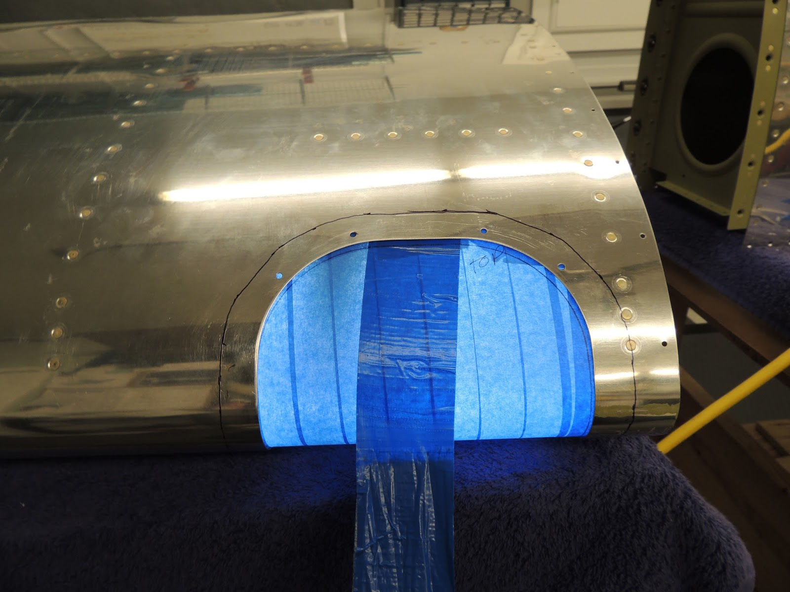
| This is the cut out in the wing leading edge for the landing light. It comes from Vans pre-cut as shown in picture. It has a pretty rough edge that will need some work to smooth out. |
 |
| To smooth the pre-cut landing light hole, I initially used a dremel with grinding wheel at a fairly low speed. I then followed up with the pneumatic die grinder and small deburring wheel. |
 |
| Using die grinder and deburring wheel to finish edge of landing light cutout. |
 |
| After deburring, I was able to get the parts for the left wing leading edge primed. |
 |
| After priming, I set up the DRDT-2 to dimple the holes in the leading edge skins. Almost all the hole can be dimpled using the setup in the picture. However, there are a few holes in the center that I could not access with this setup. The picture below will show how I setup the DRDT-2 to access those holes. I didn't take a picture, but BEFORE dimpling, I put a slight break in the aft skin edges to hopefully make for a nice flush fit later when going up to the wing spar. This is not called for in the plans, but most other times where this occurs the plans call for the "edge break". |
 |
| As mentioned above, there were a few holes in the center of the skins that I could not access for dimpling using the setup described above. To access these holes, I moved the DRDT-2 to a table that would allow me to hang the skins over the edge. With this configuration, the male part of the dimple die needs to be on the "moving" part of the DRDT-2. This works fine, it just requires a little more caution so you don't put a hole/dimple in a place where it's not supposed to be. |
November 3-5, 2017
The left and right ,outboard wing leading edge skins come from Vans with precut holes for landing lights. The typical method the lights are installed allows the inside area of the leading edge wing cavity visible around the landing light assembly. The plans advise that, if desired, the inside area (skins, ribs..) around the landing light should be painted before the leading edge is assembled. I chose to use Rustoleum flat black rattle can paint. I scuffed and cleaned the green AKZO primer that had already been applied before using the rustoleum. It turned out good, I just hope it adheres well and is durable enough for the long term. On a side note, I have never been a fan of the commonly used/stock version of lights used for the landing lights. Im sure they work great, however I just don't like the look of the round light in the oval wing cutout hole. Also, there seems to be a lot of open area around the light making the inside cavity of the wing easily visible. I have a plan that may or may not work out very well, but I think I may give it try. I will discuss and show pictures later as that progresses.
 |
| Painting landing light area of leading edge wing skin and ribs flat black to reduce glare and make the inside of the wing cavity less visible. |
 |
| I chose Rustoleum flat black rattle can paint for the interior wing sections surrounding the landing light. I scuffed and cleaned the green Akzo primer prior to applying the rustoleum. It turned out well, I hope it adheres well and is durable for the long term. |
 |
| Interior of eft leading edge skin painted with the flat black paint. |
 |
| Neighbor Scott and I install nutplates to the leading edge splice strip and the access hatch doubler plate. We used the hand squeezer to set the rivets for these nutplates. Not shown, but a technique we sometimes use to install nutplates is to hold the nutplate in position using a single (appropriately sized) cleco through the center hole of the nutplate. Both rivets are placed in position before squeezing so proper alignment/seating is maintained while setting the rivets. We "lightly" set both rivets and then remove the cleco before final setting the rivets. |
 |
| This is the access hatch doubler plate after Scott installed the nutplates. |
 |
| The access hatch doubler plate is mounted to the lower inboard potion of the left leading edge. It includes a cover plate that is used after final wing assembly to access the stall warning assembly located just forward of the access plate. I chose not to install the stall warning assembly and use a Angle of Attack indicator for stall indication/warning. The access panel will still be useful to gain access to the wing interior for routine inspection. |
 |
| The plans state to place the skins in cradles and then install and rivet access hatch doubler plate. However, I thought it would be easier to install prior to placing skins in the cradle. |
 |
| Here's the access hatch doubler plate in position on the left leading edge skin. I decided to back-rivet using the back-rivet set and plate. The back-rivet plate can be seen in position under the skin. Also visible is a "note to self" to move the back-rivet plate. Forgetting to move the plate can ruin your day very quickly. Been there done that:) This mistake seems to follow the saying, "There's those that have, and those that will!" |
 |
| Access Hatch Doubler Plate installed in underside of left leading edge wing skin. |
November 8-11, 2017
The left leading edge skin comes from Vans with two pre-drilled holes on the leading edge. Builders that want to install the stall warning unit that comes with the kit will use these holes for the installation process. I will be installing an AOA/Stall warning system as part of my proposed avionics setup so these hole will not be used. After researching how other builders "fill in" these hole, it seems most dimple the skins and install two flush head rivets. That's the route I decided to take.
 |
| Here are the two pre-punched holes in the left wing leading edge that are used for the kit supplied Stall Waring unit. New avionics systems include AOA indication and stall warning capability, so many builders choose to leave out the factory supplied Stall warning unit. In that case, these hole will need to be filled in somehow. |
 |
| To fill on the two pre-punched hole, I decide to use flush head rivets. This is the dimple die setup I used. I used the reduced diameter female die to reduce the chance of "flattening" the skin due to the curvature of the skin. |
 |
Rivets installed. Turned out ok. However, the rivet on the right was very slightly proud on one side after squeezing and I decided to angle the the squeezer slightly in order to flush the rivet head. I was able to get the rivet head flush, but due to the slight angle of the squeezer, I put a very small crease in the skin Crease is located just to the right of the rivet on the right. I will have it looked at next time I have my project inspected, but I'm sure it's well within limits, and will not be visible after primer/paint.
|
 |
| Inside view of rivets used to fill the pre-punched holes in the left wing leading edge skin. |
Next step is to insert ribs in the skin and prepare to rivet in place. The plans state to place the skins in the wood cradles and then insert the ribs. I tried that in a trial run, but found it to be a little awkward. I ended up leaving the skin outside the cradles and inserted the ribs and clecoing just the top holes of the skin to ribs. I then placed the assembly in the cradle and continued clecoing the bottom. I had read from previous builders logs that some of the holes in the forward part of the skin are a little off with the alignment of the rib holes. Not sure how this happens, but I had the same issue. It is possible with some finesse to get the clecos inserted, but I'm not sure how things will work out when it comes time rivet.
 |
| I placed the ribs in the skins and clecoed the top only prior to inserting in the wood cradles. I then placed the assembly in the cradles and continued clecoing the bottom. |
 |
| Left wing leading edge skins in cradles for riveting. This riveting could be done solo, but it sure is nice to have help! Here Scott and I use the mushroom set on the rivet gun and the angled tungsten bucking bar to set these rivets. |
November 15-18, 2017
The last piece installed to complete the left wing leading edge is the J-Channel. It is slid through a cutout in the ribs into position and then riveted. The rivets for the J-Channel are easily accessible and comfortably done solo. I used a rivet gun with mushroom set and small tungsten bucking car with an angled end to set these rivets.
 |
| Tungsten bucking bar with angled end used to set rivets on J-Channel. |
 |
| Setting rivets for J-Channel with rivet gun and mushroom set. |
 |
| This is the inboard section of the left wing leading edge showing the J-Channel installed. |
 |
| Left wing leading edge. |
 |
| This is the outboard rib bay for the left wing leading edge. This is the bay where the landing light will be mounted. The plans mention that it may be desirable to paint this area to reduce glare. It will also help to "hide" the rib bay area that will be visible to the sides of the landing light when viewed from the outside through the landing light lens cover. The landing light mounting bracket is seen here in the middle portion of the rib bay with the circular cutout. Looking closely, you will see an extra nutplate I added to each side of the bracket. I have an idea for a slightly different landing light that I am going to try. More on that later...if it works:) |
 |
| Left wing leading edge complete. |
November 27 - December 1, 2017
I've pretty much finished both wing leading edges. I still need to cut/trim/install the landing light lenses. The plans have you install the lenses after the leading edges are attached to the main wing structure. However, because of better access, it appears that it would be a little easier to install them while the leading edges are still separate. NOTE: Due to various reasons, I waited to install the landing lights until the leading edges were riveted to the primary wing structure (per the plans). As it turns out, I think this actually works great and probably better than my original idea to install the lights prior to leading edge attachment. It gives you a more secure/stable structure to work with and there is still plenty of access to the landing light assembly via the outer rib lightening holes. Once again, most of the time, it's best to just follow the plans:)
 |
| Left and Right wing leading edges are complete except for installing the landing light lenses. |
December 7-15, 2017
I mentioned earlier that I was planning on waiting to install the wing leading edges to the main wing assemblies until after I finished with the landing light lens cutting/drilling/installation. Well, because of some "issues" I had with that process (parts on order, I'll explain in detail later), I decided to go ahead with the leading edge install. Also, during this delay, I did some carpentry work and built the wing cradle (more detail later there as well), and worked on the final details of my "off plans" landing light idea (more later).
 |
| Here, Scott and I place the left wing leading edge in position on the main wing assembly. Not visible in picture , but there is a hole in the bottom of the leading edge skin that must line up with the tie-down mount that is attached to the wing spar. This hole comes pre-drilled from the factory, but needs to be enlarged by the builder. The plans reming young check that the hole does intact line up with the mount hole on the wing spar. Mine was very close, but I ended up ended up enlarging the hole in the leading edge skin slightly using a step-drill bit to get better alignment. |
 |
| Left leading edge clecoed in place to the main wing assembly. Because the wing top skins are already riveted in place, the wings are upside down here to allow access for riveting the two pieces together.. |
December 18, 2017
With the leading edge clecoed in place to the main spar assembly it was time to replace the clecos with rivets. First, the plans have you start with the outboard most rib. That's what we did and worked our way inboard. All but one of the leading edge rib flanges are riveted to the main spar using blind rivets. The most inboard rib uses universal head rivets. Also, pay attention to the blind rivet callouts on the plans. There is a size change as you work inboard due to a spar doubler that will require longer rivets. We got on a roll and almost missed that.
Note: With the leading edge attachment process moving along nicely, it will soon be necessary to move the wing assembly to some type of "wing cradle". I used a design that I have seen several other builders use. Here is a link to that process: Wing Cradle Info.
 |
| As I mentioned above, all but one rib of the leading edge is attached tom the spar using blind rivets. This is the most outboard rib shown here. Because of the tight quarters of the 3 most outboard ribs, my standard size blind rivet puller would not fit squarely on the head of the blind rivet. Here we used a technique that is described in section 5 of the plans. We used a scrap piece of trailing edge material which allows the rivet puller to "angle" slightly away form the rib web while maintaining pressure evenly across the head of the rivet. This technique works well. |
 |
| Here's our blind rivet puller in place using the technique described above. |
 |
| Here's Scott using the pneumatic rivet puller (on loan from RV builder friend.., thanks Mark!) to set the blind rivets for the leading edge to spar attachment. Due to rib configurations, as we progressed inboard , we were able to switch to the pneumatic rivet puller. This greatly speeds up the process. Be careful to pay attention to rivet callouts as you go. There are some size changes as you progress inboard, and the most inboard rib switches to solid driven rivets. We got on a roll and almost missed those changes. |
 |
| Once we completed attaching the leading edge ribs to the wing spar, we placed the assembly into the newly constructed wing cradle (Wing Cradle Info.). (NOTE: Picture above shows wing cradle before I shortened the length. See more info on this under Wing Cradle link). Next we riveted the leading edge skins to the spar flanges. The lower wing surface shown in this picture allows the rivets to be set using a squeezer. We used a hand squeezer as seen on the red stool. However, due to the upper wing skin already riveted in place, the rivets on the upper wing surface will need to be set with rivet gun and bucking bar. |
 |
| You can see the clecos in place at the far end of the picture that attach the leading edge to the main wing assembly. The rivets that will replace these clecos will need to be set with rivet gun and bucking bar because of the top wings skins that are already riveted in place. |
December 19, 2017
As I mentioned earlier, the rivets that attach the leading edge to the wing spar can be easily accessed and squeezed on the lower side of the wing. However, because the upper wing skin is already riveted in place, the rivets on the upper side need to be set with a rivet gun and bucking bar. There are several times during the build where a helper is nice to have, but not required. In the case of these rivets however, I don't see how these could be set solo. Luckily for me, neighbor Scott is always willing to help out when he's available. For those that don't have an experienced helper available, these rivets are pretty easy to set so it's not a bad time to enlist a new recruit into your project:). I would probably put them on the rivet gun side of the process initially, as I think that might require a little less training than the bucking bar. Also less opportunity to make a mistake on the side where the spar is located.
 |
| Here, Scott and I are setting the rivets on the top side of the wing that attach the leading edge to main spar assembly. I'm on the rivet gun and Scott is manning the bucking bar. These rivets are easily set and you can move along pretty quickly. However, from past experience, we have learned to not get cocky in these situations because things can go wrong when you least expect it. We took our time and focused on one rivet at a time. |
 |
| This is the rivet set I used on the skin side. It fit nicely in-between the clecos, and also did not touch the upper row of rivets that were already set. As I mentioned above, operating the rivet gun is probably the easier side of this operation as compared to the bucking bar. With the air pressure set fairly low, it's just a matter of using your fingers on the rubber part of the set to keep it in place while pulling the trigger for a second or so. |
 |
| This is the upper side of the left wing with the leading edge attach rivets set. |
January 2018
After attaching the left leading edge, I moved ahead to prepping the parts for the fuel tank. My parents came for a visit in late January and we went back and worked with the right leading edge.
 |
| Dad using the squeezer to set the rivets on the bottom of the wing that attach the leading edge. |
 |
| I got a headlight for Christmas. Works great. Wish I would have had this back when we were riveting the tailcone. |
January 1-8, 2018 - Wing Landing Light Lens
With the wing leading edge installed to the main wing structure, the next step in the plans is to fit/install the lexi-glass landing light lenses. The cutout in the wing leading edge comes pre-cut with the kit from Vans. The plexi-glass lens must be trimmed to size to fit inside the leading edges and holes match drilled to secure them. Cutting/drilling lexi-glass is a new skill that we haven't had to do yet with the project. Section 5 of the plans give several tips as to how to accomplish successfully. We had no problem with the cutting/trimming. However, when it came to drilling we did have an issue with some cracking with a couple of holes. While we followed all the recommended procedures, looking back, we think we have used a little too much pressure on the drill which resulted in the two cracked holes. After ordering a replacement lens, we were more careful the next time. We made sure to go slowly and to use less pressure to let the bit do the work. Everything turned out fine with no cracking.
 |
| To mark the lens for the initial cut, the lens is placed on the outside of the leading edge. The plans give dimensions for these cuts. However, because this was my second time accomplishing this task..due to cracks during my first attempt, I made the cuts a little different than the plans described. Hard to explain but rather than marking the width on both sides of the lens, I adjusted the outboard edge so that no cut would be necessary. Therefore, I only had to make a "width" cut on the inboard section. If you go this route, be aware of edge distances of the screw holes that will be a factor during the next cuts when the backplate dimensions are laid out. I had my scrap piece to study, so it made this process a little easier. |
 |
| To cut the lens, I used a dremel with this thin cut blade. I worked slowly making several shallow cuts increasing depth with each subsequent cut. It appears, using this method, the blade half cuts/melts the plexi as you progress. This worked well for me and I had no issues, although I didn't try any other method so I don't have any comparison. I did use a portable heater to keep the lens nice and warm during these cuts. |
 |
| After the initial "outside" cut is made to the landing light lens. It is covered with tape to prevent scratching and also to allow pen marks to be made, and easily visible. |
 |
| After the initial cut is made, the lens is placed inside the leading edge. The plans give the idea to apply tape as shown here to help "pull" the lens tight to match the shape of the leading edge skins. There is also enough room via the holes in the outside rib to reach in and push the lens for behind. Extra pair of hands definitely comes in handy here. The goal is to get the lens as tight against the skins as possible before the trace lines are drawn. |
 |
| Here's the backing plates that will eventually be attached (via double side tape, or equivalent) to the lenses. |
 |
| Here, the backing plates are clamped in place using the the lines were traced from the cutout in the leading edge. Another line is then drawn off this back plate and further trimming is accomplished. This is where (the first time when I followed the plans for the marking/cutting) I ended up with the a very small edge distance from one edge of the backing plate. I think this picture is from that attempt, and the edge distance issue is seen on the right side of the back plate. Edge distance probably not an issue in this case. However, since I ended up doing this step over due to cracked holes when drilling, I modified the process on my second attempt and I ended up with more edge distance. |
 |
| There are several methods I researched for drilling the plexiglass lenses. I ended up buying actual plexi-glass bits. |
 |
| Here was our first attempt at drilling the holes in the lenses. There are eight holes total ( 4 top, 4 bottom) that need drilled in the lenses. We ended up with cracks on the last two we drilled. I think we just got a little too confident, and maybe applied too much force with the drill bit. We learned the hard way. Let the bit do the work and apply just enough force to keep the bit in position and moving forward. Additionally, because we still had the tape in place on the lens during drilling, we didn't find out about the two cracks until all holes were drilled and we removed the tape. Not a nice surprise. On the replacement lens we were much more careful and had no issues. |
 |
| Next, the previously drill holes need to be countersunk to fit the dimpled screw holes on the leading edge skins. Here, we are "practicing" using the lens with the cracked holes. This technique did work for us and we used it on the replacement lens. We did have some tape applied to the replacement lens to help reduce scratching. |
 |
| Scott countersinking the holes in the lenses. Again, light pressure and low rpm worked well for us. |
 |
| Once the holes in the lenses are countersunk, the backing plates are attached to the lenses. The plans recommend double-sided tape (or equivalent) to accomplish this. I opted for "or equivalent" and used proseal. In the end, the proseal worked ok, although I'm not sure I would use it again. Even though, I had tape in place to keep the proseal at bay, I still need up with it in areas go the lens where it didn't belong. Additionally, the squeeze out from the edges of the backing plate were a little more difficult to remove than I had planned for. I ended up having to use Naphtha and Q-tips to clean that area, and even then there was a slight "haze" left behind from either the proseal or the naptha. Luckily, I was able to get the lenses back in good shape using the Novus products shown below. If you decide to use the proseal route, the plexi must be scuffed sufficiently to allow the proseal to "grab". I use 150 grit sand paper in the areas where the proseal would be located. Also visible in this picture, you can see the area outside the backing plate is painted black. During trial installations, I noticed that edge of the plexi is visible from the the outside. I scuffed and painted that area black and I think it turned out well. |
 |
| I discussed above that I had some areas on my landing lenses where the proseal left some "hazy" areas where it made contact with the plexi. I used the products shown here and had pretty good success. It was a tedious process as I used small pieces of old t-shirts and even Q-tips to remove the hazed areas around the backing that would be visible from the outside. |
 |
| The landing light lens after cleanup and final installation. Overall I'm pretty happy with the way they turned out. However, even after all the effort to try and get the lens as tight as possible to the leading edge skins during the fabrication process, I still ended up with slight (apprx. 1/16") gaps in certain areas. The gaps were pretty consistent on both wings. Not easily visible in the picture, but the gaps are located on the lower portion of the leading edges just below and aft of the tip of the leading edge. The gap continues aft for approximately 1" and then it is a tight fit. I have heard that other builders have experienced the same issue. I will leave for now, and decide later on how to seal the gaps. |
 |
| Left leading edge complete with landing lights installed. |
January 2018
Left and right wing leading edges complete, and attached to primary wing structure.