Aileron Actuation (Wings)
This section covers the aileron actuation process that takes place in the wings. I will cover further aileron actuation processes in the section in which they are located, i.e., Aileron Actuation (Fuselage). Time line for this section is difficult to track. I mostly worked on pieces and assemblies over several work periods when I had extra time.
 |
| The plans include a paper template that is used to ensure holes are drilled in the proper location on the aileron push tubes. |
 |
| Dad was in town town and helped out. |
 |
| I wanted to prime the insides of the torque tubes so I pushed a piece of scotchbrite pad back and forth through the tube a few times to scuff up. |
 |
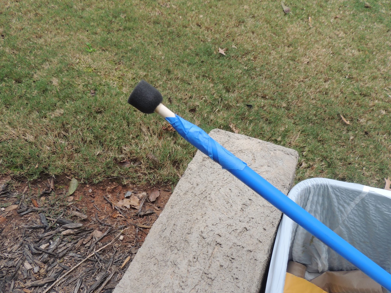
| Next, to apply primer inside the tube I tried using this sponge brush. I didn't work very well at all as the sponge part kept coming off inside the tube. It just made a big mess. |
 |
| Like I mentioned above, the sponge brush didn't work out too well. I ended up just pouring the primer in the tube and rolling/tilting until the inside was fully covered. |
 |
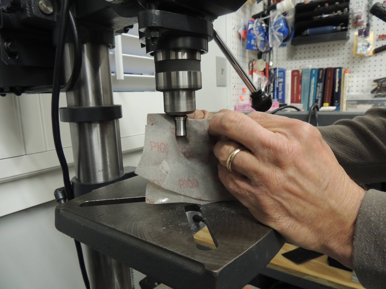
| This is one of the threaded rod ends that gets inserted into the bellcrank to aileron pushrod. I found the diameter of this part to be slightly too large to fit inside the pushrod. I decided to use the drill press and a file to reduce the diameter. To prevent damage, I placed two nuts on the threads before chucking the part in the drill press. |
 |
| Using the drill press and file kind of like a lathe to reduce the OD of the threaded rod end piece. |
 |
| Used sandpaper for the final finishing. This shows 150 grit, but eventually worked down to a finer grit for a nice smooth finish. |
 |
| Drilling holes for the rivets that will be used to secure the threaded rod end to the push-rod. Proper hole layout important here. No template in the plans like for the large torque tubes so you have to figure it out on your own. I found it worked much better to only drill one hole at a time then rotate the tube to the next hole, i.e., don't drill all the way through. When I tried to go all the way though the part, the holes ended up being slightly mis-aligned. With a better setup, you may get better results. |
 |
| My plan to prime the inside of the tubes was to install only one of the threaded rod ends to act as a stopper, and then pour primer inside the tube. |
 |
| Occasionally, I find it can be difficult when inserting a rivet through pieces of thicker material. Sometimes it seems the rivet needs just a little extra push to get to the fully seated position. Instead of drilling out the hole, I remove one of the dies from the squeezer yoke so you are left with an empty hole. This will allow an opening for the shop head end of the rivet during insertion. I then use the squeezer to "gently" push the rivet in place. No force here, just a little extra push. If force is required, something is not right and should be looked at. |
 |
| Using the squeezer as described above to "push" the rivet in place. |
 |
| Will add more info later here, but a quick note. Using the C-Frame to set these rivets worked well. However, it is best to have a helper . One person to operate the rivet gun and one to hold/stabilize the push-rod. The push-rod has a tendency to want to roll during riveting. This pic shows me solo, but neighbor Scott was helping during the actual riveting process. |
 |
| Like I mentioned above, I only installed one of the threaded rod ends to the tube to act as a cork. I then poured in primer and slowly rolled/tilted until the inside was covered. Of course the inside of the tube had already been scuffed and cleaned before this step. |
 |
| When I felt the inside of the tube was sufficiently covered with primer, I poured the out the excess. |
Aileron Bellcrank
My assembly of the aileron bellcrank was slightly off plans. My process, where possible, was to add washers anywhere that a bushing or rod end bearing makes contact with a powder coated, or aluminum part. In the case of the aileron bellcrank, there are a few areas where this occurs. First, the brass bushing that the aileron bellcrank rotates "about" is held in place between two aluminum brackets mounted to the wing spar. The plans have this brass bushing in direct contact with the aluminum brackets, which I'm sure is perfectly acceptable. However, I thought a better method might be to add washers for these contact areas. To accomplish this, it is necessary to to reduce the length of the brass bushing, and also the length of the bellcrank the brass bushing is inserted. This involved a little math to determine about how much "length" to remove to allow for the width of the washers. Several test fits followed to check for the desired clearances. I only removed a very small amount of material at a time, especially on the powder coated bellcrank, to ensure I didn't remove too much.
 |
| The proper assembly of the aileron bellcrank is for the brass bushing to be inserted into the powder coated bellcrank part. The brass bushing needs to be slightly longer than the bellcrank so that when positioned between the two mounting brackets on the wing spar and tightened to spec, the brass bushing will remain stationary with the bellcrank rotating about the bushing. As discussed above, I added washers to the areas where the brass bushing contacted the aluminum brackets. |
 |
| I went back and forth on the type of lubrication to use for the bellcrank/bushing contact area. I narrowed it down to Lubriplate grease and LPS2 spray lubricant. I decided on the LPS2. My thought was that if I used the Lubriplate, it would be very difficult to re-apply once the bellcrank assembly was in service. You would pretty much have to disassemble to re-grease. Granted, the part could probably go for many years with needing service. Using the LPS2, I can fairly easily gain access to the bellcrank through an access panel in bottom wing skin. Then I use the spray tube to apply the LPS2 to the upper potion of the bellcrank/bushing and let gravity do the rest. |
 |
| Test fitting the aileron bellcrank in the left wing. You can see the washers I added between the powder coated bellcrank and the aluminum brackets. The slight gaps between the washers and the bellcrank ensure the bellcrank rotates freely about the brass bushing, while the bushing remains stationary. |
Once the bottom skins for the left wing were riveted in place, I final installed the aileron actuation assembly. In the photos below, you can see where I added washers to areas that contact the powder coated bellcrank. To maintain factory fit of the bellcrank assembly (no spreading/binding etc.), in some cases I used longer bolts and thicker/thinner washers to ensure proper grip lengths were maintained.
After finally getting the bottom wing skins riveted, I did another check of aileron and actuation rigging using the jigs supplied with the kit. Amazingly, somehow, everything turned out pretty good.
 |
| The bellcrank jig can be seen here with the blue plastic still attached. It is used to ensure the belcrank assembly, and forward torque tube assembly (located at the inboard section of the wing), are in the neutral position. The large torque tube can be adjusted slightly if needed to achieve the proper measurement required at the forward torque tube assembly. Once the neutral position is set, no further adjustments to the torque tube to bellcrank can be made. At this point, a second jig is placed on the outboard section of the aileron to set the neutral position of the aileron. |
 |
| The aileron jig is used to set the neutral position of the aileron. Using this jig in conjunction with the bellcrank jig, also in position, allows you to set the neutral position of the aileron. This is accomplished by adjusting the bellcrank to aileron pushrod length, payiing attention to rod-end bearing thread engagement, until the aileron matches the jig position. The aileron and bellcrank are now theoretically in the neutral positon. The next big question is straight did you build your flaps and ailerons:) If there is a bit of twist in either, it will become apparent at this point because the flap/aileron intersection may not align. |
 |
| With both the bellcrank and aileron jigs in positon, you will be able to see how the "straight" the intersection is between the flap and the aileron. If the aileron or flap has a twist, it may show up at this point. I say "may", because it could be possible, I suppose, that the flap could have a twist up, and the aileron could have a twist down, and the intersection would still appear nice and straight:) Not sure the situation in my case, but somehow, miraculously, the trailing edge of the flap/aileron is pretty straight...both wings. Not out of the woods yet though....still have to add the fiberglass tip! In theory, if Vans' jig system works, the fiberglass wingtip should be pretty close. We'll see:) |