Fuselage Kit - Ordered Sep 29, 2018 : Arrived Dec 28, 2018
 |
| Too late to turn back?? :) |
June 2019
While finishing up some wiring, and bottom skin riveting on the right wing, I decided to start some fuselage work. My parents were coming from out of town to visit, and thought it would be a little more enjoyable than wing skin riveting.
 |
| Here's the parts for the first section in the plans for the fuselage. Like always, there's a bit of parts prep, and of course, the ever popular deburring to take care of before you can start the fun stuff. |
 |
| Mom helping with the blue plastic removal. |
 |
| New addition to the family, Georgie Pearl, enjoys spending time in the shop. |
 |
| Dad and I used the c-frame to rivet the first parts of section 25, the Fwd-Mid Fuse Bulkheads. |
August 2019
 |
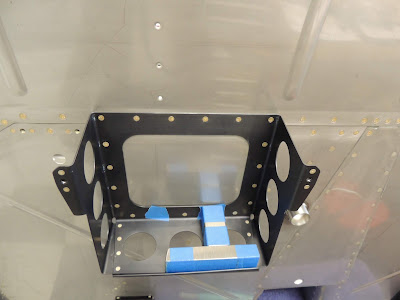
| This is right right cover rib with the bearing bracket attached. For some reason, the bearing would begin to bind during riveting. I tried several times using several different methods and order of setting the rivets, but at some point, the bearing would always begin to bind. I had no trouble with the left assembly. After a few times of setting and drilling out rivets, I decided to order new parts ..cover rib included, because I felt the shop heads of the rivets used to attach the bracket stretched the thin metal of the web of the rib. The binding wasn't terrible but I felt it was enough to cause unnecessary wear. The new parts went together with no issues so who knows..just something to watch out for. |
September 2019
 |
| Here's the Mid-Fuselage section pre-assembled with clecos. This pre-assembly helps visualize how the parts go together and catch possible tricky areas before final assembly. |
October-November 2019
 |
| After we disassembled the parts of the mid- fuselage, after the pre-assembly, it's time once again for everyones favorite part of the build process...DE-BURRING! Many hours are spent on this boring, repetitive, but necessary part of the project. |
 |
| The parts for the mid-fuselage section post de-burring ready for prep and primer. |
 |
| Neighbor Scott demonstrates the proper protective gear to be worn while working with alumiprep and alodine. Ok, on further observation, he may be missing a few items. This was our first time using the alumiprep/alodine prep method before priming. It will also be our last. The reason I wanted to try this method was I thought it would save some time during the prep procees for priming. I will show pictures and discuss this further in the PRIMING section of my blog. |
November 2019
November 15, 2019
Since neighbor Scott felt it was more important to take a family vacation to Mexico rather than airplane building, I was forced to proceed solo:)
The bottom skin riveting is pretty much a two person job so I moved ahead a few pages in the plans to find solo work.
The baggage rib section includes a few pieces that are assembled prior to riveting in place on the bottom skin. First is the Step Attach Weldment. This piece is white powder coated steel and is primarily used on the Tri-Gear models, but the plans state it can be used by the Tail Dragger builders if desired.
There is something to consider prior to riveting this part to the baggage rib using the sequence in the plans. There is baggage rib that is installed a few steps later that would be much easier without the white powder coated piece installed. I didn't catch this until I got to that point and discovered the three rivets that will be difficult to set. I visited some of my favorite builder blogs and found that Steve had covered this on his site (HERE). Wish I would have reviewed his site prior to following the plans. Steve has a great blog for his build and I'm glad he's ahead of me so I can use it as a reference. Check out his fuel tank construction (HERE) They are a work of art:)
However, since I followed the plans, I will not remove the white powder coated Step Attach Weldment to make it easer to set the three rivets for the baggage rib. They are not impossible to set, and many builders have done it successfully. Another one of my favorite builder blogs is VJ's. He has great pics with annotations and his work looks outstanding. VJ followed the plans for this step as he describes (HERE) He mentions the limited access for the bucking bar when attaching the F-01424-L baggage rib. Looks like he did did a nice job. Hope mine turn out that well.
Basically, if I had it to do again, I would do this: Skip step 8 on page 26-17, then continue following the plans all the way through step 8 on page 26-19. After riveting the three rivets that attach F-01424 to F-01495, go back to step 8 on page 26-17 and rivet F-00016 (white powder coated part) to F-014223B.
 |
| The white powder coated piece is the Step Attach Weldment. There are five rivets used to attach bit to the outboard baggage rib. The plans give the option of using cherry max rivets for all five if desired. Two cherry max are pretty much require due to restricted access, but the other three are fairly easy to set solid rivets. (See description above regarding delaying the installation of this piece) |
 |
| I used my tungsten bucking bar with the angled end to set the three solid rivets. |


 |
| There are three rivets at this stage that attach the F-01458 to the F-01423B baggage rib. The plans call for LP4-3 rivets here. These rivets are fairly accessible, so I used AN470AD4-4's for two of the three instead. The angle of my tungsten bucking bars did not work. I used this one (HERE) |
 |
| Three rivets attach the small horizontal bracket to the F-01458. One is a LP4-3, the other two are AN470's. If squeezing these rivets, one of them is difficult because the angle on the F-01458 restricts the squeezer dies. I don't have pics, but I ended up back-riveting the two AN470's with the C-Frame. |
 |
| Here, the F-01424 baggage rib is riveted to the F-01495 step attach rib. These are the three rivets described above that would be easier to set if you don't follow the sequence in the plans (pg. 26-17 rev.0). |
 |
| Shop side of the three rivets with limited access. I'll post pics when I get them set. |
November 18, 2019
 |
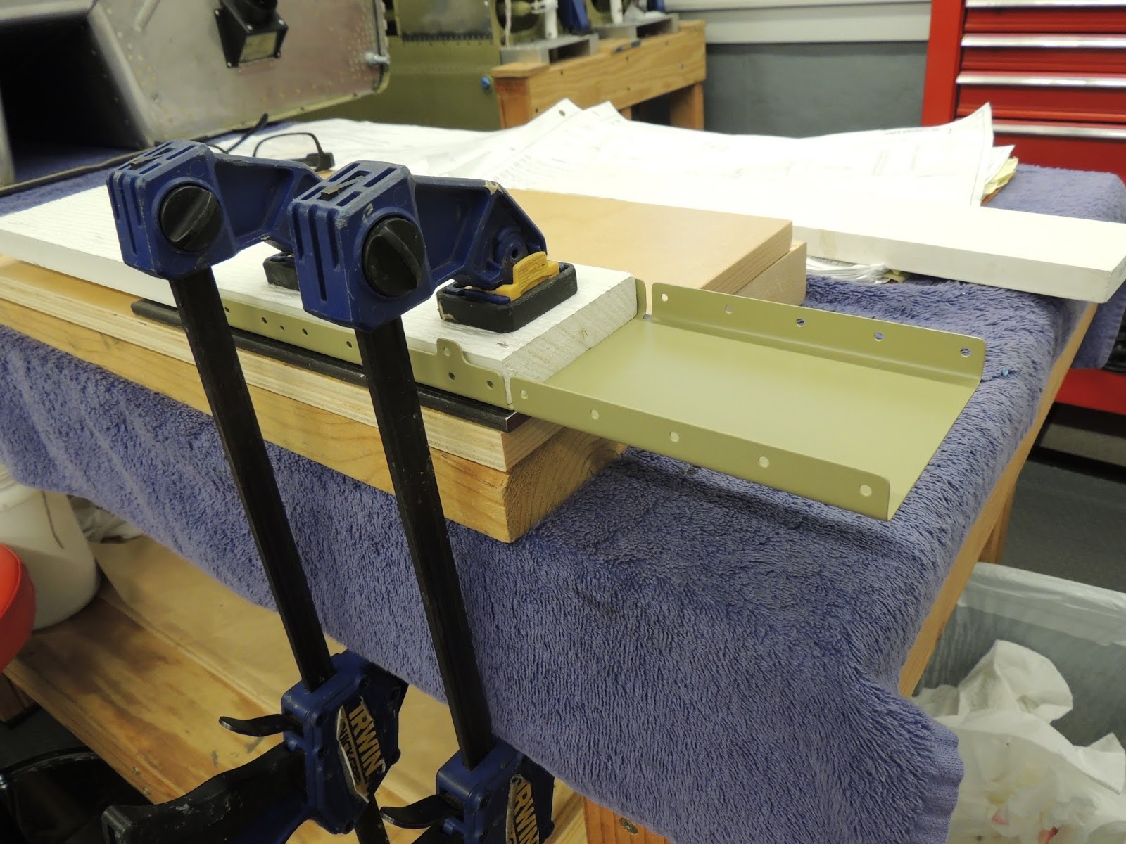
| The F-01424 baggage rib gets riveted to the F-01495 step attach rib using three AN470 rivets. As described above, there is not much room for your hand and bucking bar on the shop side of these rivets. |
 |
| Due to the different angles of this assembly, it is difficult to secure for riveting. I found the setup shown above worked pretty well. |


November 22, 2019
 |
| Once the center bottom skins were riveted, it was time to rivet the aft gear brace assembly to the seat rib web. LP4-3 pulled rivets are used here due to inaccessibility with rivet gun. |
 |
| Most of the LP4-3 rivets are easily accessibly with the rivet puller. However, there area couple where you must get a little creative to get the puller in the proper position. I found the position above worked for me. Can't see in the picture, but I also used a small piece of modified trailing edge material (as described in section 5 of plans manual) over the rivet head to keep it flush with the web of the rib. |
December 2019
 |
| When riveting the two center baggage ribs to the F-01405 bulkhead, I was not happy with the rivet gun/rivet set alignment on the rivet head. With the routing angles that were installed earlier in the chapter in place, it was difficult to properly align the rivet gun. As seen above, I removed a couple of the routing angles by drilling out the three rivets used to attach it to the baggage rib. I did this for the two baggage ribs although only one is shown above. |
 |
| Here's the routing angle being removed from the baggage rib. Because I had placed the manufactured head on the baggage rib web, it was easy to drill and snap the rivet head off which allowed the routing angle to be removed with no damage to the rib web. |
 |
With the routing angles removed, I was able to get good alignment with the rivet gun and set.
NOTE: For future builders, You may want to consider delaying the installation of the routing angles until the baggage ribs are installed. |
 |
| Once the two inner baggage ribs a re riveted to the bulkhead you can easily install the routing angles. Note however the sequence of riveting the baggage ribs to allow room for the rivet gun needed to rivet the routing angles. |
 |
| Once the rivets for the baggage rib were set with the manufactured heads on the flange side as described above, we riveted the seat belt lug brackets to the F-01405 bulkhead with the manufactured heads on the bulkhead side. Not the way I typically like doing it, but in this case I think it worked out best. You van see in the picture below the limited space for the rivet gun and set if you decide to place the manufactured heads on the flange side. |
 |
| Next, Scott and I positioned the assembly on the workbench to finish riveting the baggage ribs to the bottom skin. |
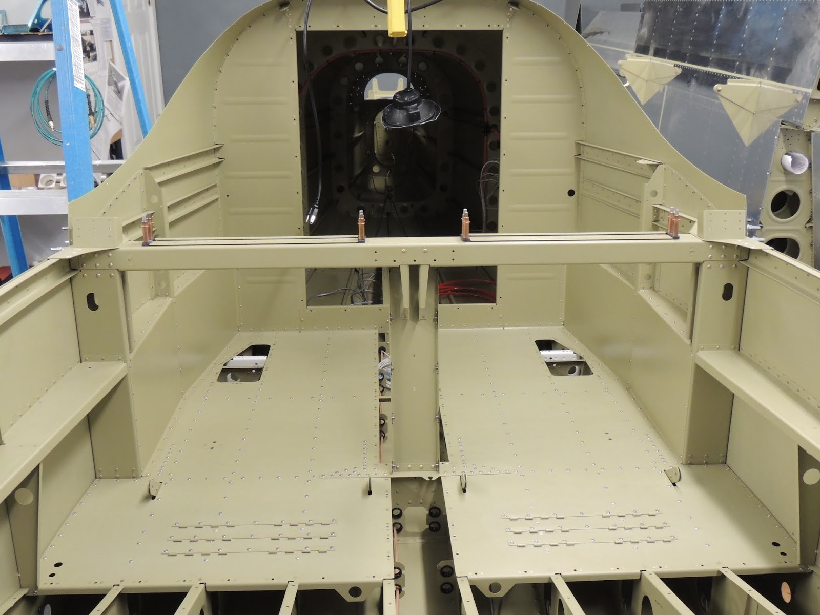
The following pictures show what you end up with after completing Section 26.
The Mid Fuse Lower Structure.
December 2019
 |
| Section 27 begins as all the others; parts prep, deburring, and priming. Additionally, this section has a fair amount of machine countersinking required for the parts that attach to the firewall. I looked through the section and pulled all the parts that required countersinking and accomplished prior to priming. I've mentioned before that machine countersinking is one of my least favorite things to do, especially when the countersink is required for a dimpled skin. Countersinking for a rivet isn't too bad because you can see exactly where you stand with the depth of the countersink by testing with the rivet. Countersinking for a skin is a little less exact and requires more technique, e.g., extra clicks on the micro-stop, and dimpled test pieces of the correct skin thickness. |
 |
| Here Scott uses the C-Frame to back-rivet the support angles to the firewall. This process can be done solo, but is much easier to have a partner holding the parts in place to ensure there is no movement and possible damage to the material. Someone has to take the picture though:) |
January 2020

 |
| Here, we're riveting the stiffener to the right forward bottom skin. We once again were able to use the c-frame with great results. This will essentially be the floorboard where your feet will rest when seated. Below this piece of aluminum will be nothing but thin air:) |
 |
| Left forward bottom skin with one side of the muffler shroud pro sealed and clecoed in place. |
 |
| Right forward bottom skin with one side of the muffler shroud pro sealed and clecoed in place. |
 |
| Scott using the c-frame to set the rivets on the muffler shroud. This is easier with two people. One to pull the trigger on the rivet gun and another to secure the assembly so it doesn't slide off the rivet set. To use the c-frame, the skin needed to be elevated to match the height of the lower set. |
 |
| This is about as far as you can use the c-frame before access and alignment becomes an issue. |
 |
| We then turned the assembly on its side and used a rivet gun and bucking bar. for the remaining rivets. We mostly used a variety of tungsten buck bars, but for the last couple of rivets used the bucking bar shown here. |
 |
| To keep the assembly from moving around while setting the rivets on the muffler shroud sides, we secured it to the work bench as seen here. |
 |
| Left and right muffler shroud sides riveted to the bottom skins. |
 |
| The fuel pump bracket is riveted to the muffler shroud top skin or ramp as the plans call it. |
 |
| The plans call for -3 length rivets to attach the fuel tank bracket to the muffler shroud top skin. I almost always use a rivet gauge (not the one seen in pic,This One ) to check the rivet lengths. Here I found the -3s to be a little short. Sure they would have been fine, but I took the opportunity to use the next size rivet with a pre-squeeze to ensure a nice tight fit in the hole. |
 |
| To use the c-frame, once again, the assembly needed to be elevated to match the lower set height. |
 |
| Here's my setup to elevate the skin assembly yo match the lower set height of the c-frame. |
 |
| In some cases, I use this mushroom type set in the c-frame vs. the straight set. |
 |
| Fuel pump brackets riveted to the muffler shroud top skin. |
March 2020
 |
| Riveting the muffler shroud ramp to the muffler shroud sides. I initially started this process using the rivet gun and tungsten bucking bar. However, after setting a few rivets I noticed there was some slight separation between the ramp and the flanges of the sides for a few of the rivets. Not all just a few. I continued riveting with gun and bucking bar. When I finished, there were about six rivets where the separation occurred. Not necessarily a terrible thing I don't think, but I wanted to see if I could make them a little better. I thought I would drill out one rivet, and if my solution worked, I would continue with the others I wasn't happy with. |
 |
| After drilling out the first rivet I discussed above, I replaced the rivet and used the squeezer to just barely set the rivet. Making sure the gap was eliminated. I then went back to rivet gun and bucking bar. I ended up replacing all six rivets I wasn't happy with. All turned out with good results. BTW, the rivets drill out nicely in the stainless material. The holes don't seem to "enlarge" from the driven rivet as they do with the thinner aluminum. That makes setting the replacement rivet much easier. Although, as my normal procedure for all drilled out rivets, I still attempted to "pre-squeeze" the replacement rivets as much as I can to get a nice tight fit in the hole before setting. |
 |
| The end rivet located in the narrow area can be a problem child. I've seen other builders use a variety of techniques to set this rivet. Here's what I ended up using. I set the rivet as much as I could, which was not much, until I could get my thinnest tungsten bucking bar, or no-hole squeezer yoke (whichever came first) to fit over the rivet head. This worked "ok", but wasn't able to get the rivet set as much as I would have liked without risking damage to the parts. I'm comfortable with it though. |
 |
| The last rivet on the top row is the problem child discussed above. If I was doing over again, I might research the option of using some type of approved blind rivet in that location. |
 |
| Here's the completed muffler shroud assembly. If you stick with the plans exhaust system, there will be a single pipe routed inside this assembly. Some builders are using a popular dual exhaust system instead of the stock setup. There may be a slight performance increase, although I understand the dual pipes do not fit in the tunnel. This does not seem to be an issue, however, I am planning on using the stock system. |
 |
At this point, the firewall assembly is placed in position over the left/right bottom skins and muffler tunnel assembly.
Once again, fuel tank sealant is used to seal the areas where smoke/fumes may enter the cabin area. |
 |
| There is a mix of solid and blind rivets used to attach the forward portion of the muffler tunnel to the firewall assembly. The ones shown in this picture are solid and I used the long back-rivet set with good results. Scott was on the shop heads with a tungsten bucking bar. |
 |
| Scott on the shop head of the rivets used to attach the muffler tunnel top skin to the firewall skin. |
Firewall Vent Assemblies
UPDATE: When assembling these vent assemblies, look ahead to section 48 in the plans. There is a cover plate that is added to the right vent assembly (as of my assembly date of Mar 2020). It would be easier to accomplish at this stage instead of later. Here is a picture showing the page from section 48. I found this after I had already installed the the vents on the firewall, but I went ahead and modified the right vent per the section 48 instructions. See pictures at the end of this section.

 |
| This is the left vent assembly. Pretty easy assembly using pulled rivets. The stainless hinge and flapper door are attached to the arm using stainless rivets. These are harder than the aluminum and require a little bit more effort to set. We tried the hand squeezer first, but didn't like how it was going. We resorted to the trusty C-Frame for back-riveting and it worked well. As seen in the pic, the vent housing is colored black. I "home anodized" these and was happy with the results. See process here: Anodizing |

 |
Here is the left vent door clecoed in place. Something I noticed when closing the door was that to get the door to the fully closed position required just a little extra force. Not much, but you can feel just a little "spring back" as the door goes to to the fully closed position. Looking closer at this, the "spring back" is due to the lower hinge and upper hinge not being on the same plane. This is because of the thickness of the vent door attached to the upper hinge. I experimented a bit by placing the hinge template, that was used to match drill the hinges, under the lower hinge. This allowed the door to close much easier with no spring back as the door went to the fully closed position. Almost too easily, and I wondered if the Vans designers preferred the slight spring back tension on the hinges. I noticed that with the shim installed, the hinge assembly was under no tension when closed and may have a tendency too vibrate and cause wear to the hinge/pin assembly. With no shim, per the plans, the hinge/pin assembly is under a slight amount of tension which prevents any vibration. After too much consideration on this, I went ahead and installed per the plans.
UPDATE: AS DESCRIBED LATER IN THIS SECTION OF MY BLOG, THERE IS A MOD THAT IS MADE TO THE RIGHT VENT ASSEMBLY THAT REQUIRES A COVER PLATE ADDED. I TOOK THIS OPPORTUNITY TO ALSO MODIFY THE LEFT AND RIGHT VENT HINGES BY ADDING THE SHIM DISCUSSED ABOVE. I WILL SHOW THIS MOD AT THE END OF THIS SECTION.
UPDATE TO UPDATE: AFTER FURTHER REVIEW, THIS COVER PLATE IS INSTALLED ONLY IF YOU ARE USING THE EXHAUST SYSTEM PER THE PLANS. I USING SOME OTHER SETUP, THIS COVER PLATE MAY NOT BE REQUIRED. ADDITIONALLY, THE EXHAUST SYSTEM FOR THE NEW IO-390 -EXP119 MAY/MAY NOT REQUIRE THIS COVER PLATE. |


UPDATES:
AS MENTIONED ABOVE, THERE WERE A COUPLE THINGS I DECIDED TO DO TO THE VENT ASSEMBLIES.
FIRST, The issue of the slight spring back of the vent doors when going to the fully closed position. I added a shim, template used top match drill hinges, under the lower hinge sections of L/R vent assemblies. The door now goes to the fully closed position very smoothly with no spring back tendency.
 |
| Here is the template used to match drill the holes in the vent hinges. I used it as a shim under the lower hinge sections. |
 |
| This is where I added the shim. |
 |
| Shim installed under lower hinge. I modified both left and right vent assemblies. |
UPDATE:
The second thing I did to the vent assemblies was to add a cover plate to the right vent.
This mod is described in section 48 in the plans. There is a cover plate that is added to the right vent assembly (as of my assembly date of Mar 2020). It would be easier to accomplish at this stage instead of later. Here is a picture showing the page from section 48. I found this after I had already installed the the vents on the firewall, but I went ahead and modified the right vent per the section 48 instructions.
UPDATE TO UPDATE: AFTER FURTHER REVIEW, THIS COVER PLATE IS INSTALLED ONLY IF YOU ARE USING THE EXHAUST SYSTEM PER THE PLANS. I USING SOME OTHER SETUP, THIS COVER PLATE MAY NOT BE REQUIRED. ADDITIONALLY, THE EXHAUST SYSTEM FOR THE NEW IO-390 -EXP119 MAY/MAY NOT REQUIRE THIS COVER PLATE.
 |
| This is the cover plate that gets attached to the right vent assembly per the plans in section 48. We discovered this just after we assembled and installed the vents in section 28. Since we couldn't see any reason not to modify now, we went ahead and made the modification. |
 |
| Two blind rivets removed. |
 |
| Cover plate installed and sealed with high temp black RTV. |
 |
| Setting the bottom rivets of the battery box required some thought. Luckily, one of my "go to" builder sites was able to help out. Steve's website is very informative, and he does a great job documenting with detailed pictures and explanations. Here's a link to Steve's site (with credits to Tim for the idea) for the process shown in the picture above Steve's RV-14 |
March 17, 2020
April/May 2020
June 25, 2020
 |
| As I mentioned before, I have a neighbor that just happened to be in the wrong place at the wrong time five years ago when I ask him to help unload the empennage kit. He became interested in the project and has been involved in all parts of the build since that day...even deburring! Well it took five years, but it finally happened. On the day of the "Big Join", Scott finally showed up dressed in the uniform of the day (think Gunny Highway, Heartbreak Ridge:) Totally unplanned, but good for quick laugh. |
July 2020
Initially, I skipped section 31 because I wanted to complete section 32, the Baggage Area, so I could paint the interior.
The first step in section 31 is installing the fuel line brackets using LP4-3 pilled rivets. As seen in the picture below, access to some of these rivets can be limited. In this case, a bolt head restricts access to the pulled rivet shaft. I added nuts as spacers to allow my rivet puller access.
Off Plans Tie-Down Rings
Off Plans - Extra Snap Bushing Clips
The following pictures show the fuselage interior paint process. I have been able to avoid building a paint booth in my shop up until this point in my project by paining outside when weather permits. However, now that the project is larger it would be difficult to move outside. Plus, with summer temps in the mid 90F range and high humidity, I felt painting inside was a better option.
Click
Here to see my paint booth setup.
October 2020 - Brake System
 |
| The Rudder Pedal Assemblies have three positions available for setting fore/aft. Builder height and pilot preference determine which setting to use. Without the seat in place, it was a little difficult to determine which one I preferred. I imagined the approximate seated position and decided I would choose the most aft setting. I'm 5'10" on a good day for perspective. |
 |
| I used the brake line kit from Aircraft Specialty / TS Flightlines. Both Tom and Steve are great to work with and produce an outstanding product. I also used their fuel line kit. This picture shows some of the stainless braided hoses that replace the plastic hoses that come with the kit. I will clean the routing up when I'm a little further along. |
 |
| Overkill here, but I noticed a slight amount of movement at hose/fitting connection when the brake pedals were moved. I thought I could reduce some of the stress by spreading the load. I cut a slit in in a rubber hose and positioned it over the transition area. Lightly secured with clamps placed over the metal part of the fitting. Like I said, complete overkill but I couldn't resist. |
October 2020 - Rudder Cables
 |
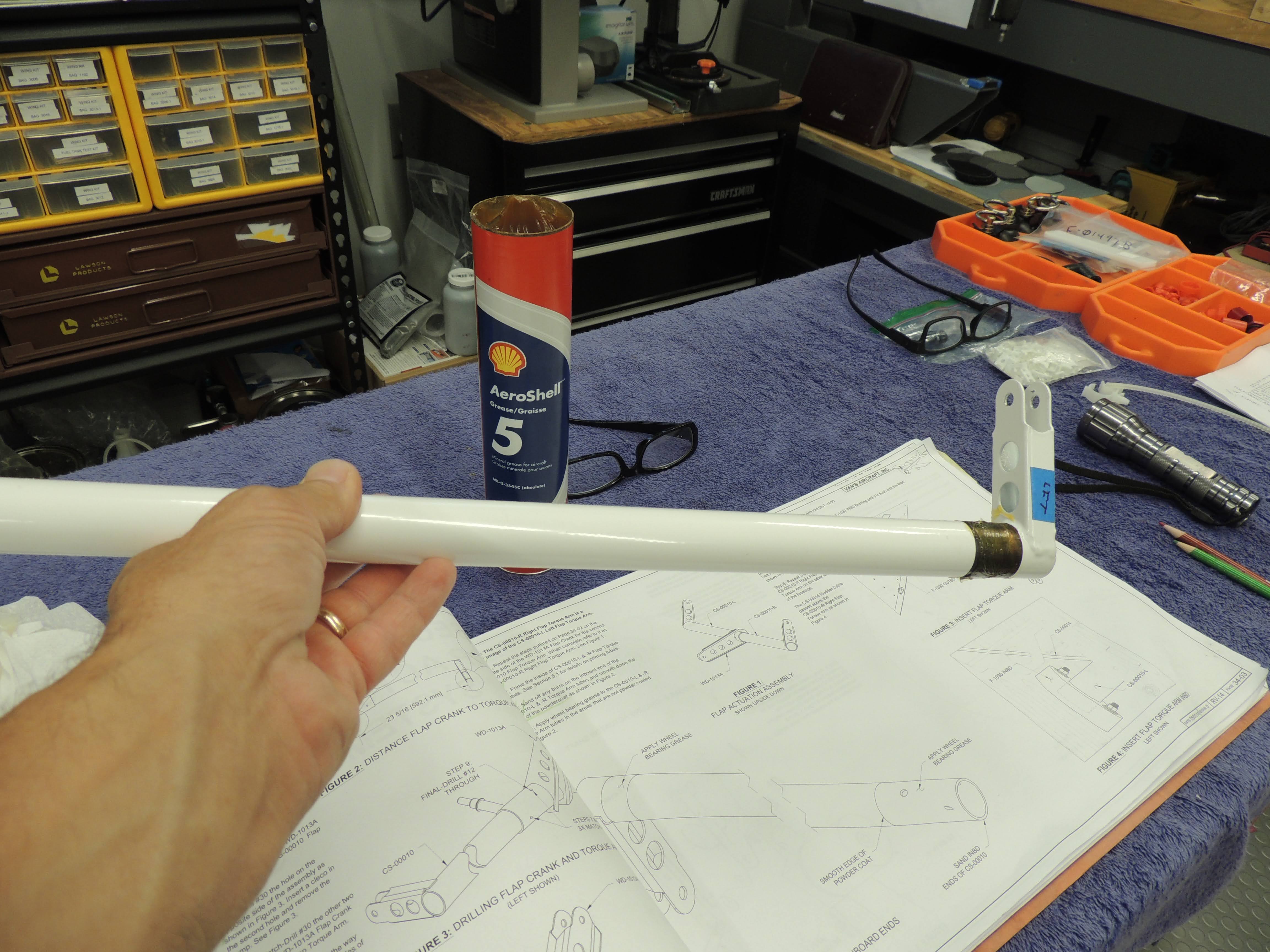
| I've had mixed results throughout the project priming inside torque tubes. My usual process is; scuff, clean, pour in primer, twist-rotate-swirl, and pour out excess. It can get messy and sometimes difficult to get full coverage. Because the Flap Torque Tube is relatively short, I thought I'd try something different. I generously sprayed rattle can self etching primer inside the tube followed by the twist-rotate-swirl, pouring out excess process. I actually worked pretty well. It seemed to stick better as it flowed through the tube compared to the Akzo primer. Who knows about long term adhesion/protection, but I think it will be ok is this situation. |
 |
| If you plan on installing the optional Flap Position Sensor, it's a good idea to drill the hole for the pushrod before the Flap Crank is installed. |
October 2020


