October 9, 2018
Started construction of the ailerons.
 |
| Pics above and below show the parts for the left and right ailerons. There was a fair amount of metal work involved to get the skin stiffeners cut and shaped from a piece of larger stock. Nothing difficult just time consuming. Now begins the deburring process. |
October 12-14, 2018
 |
| Like most other components of the build, the ailerons get put together and taken apart a few times before actual riveting takes place. I found the plans for the ailerons to be a little hard to follow in places and had to read/re-read, as well as read ahead to figure out what the sequence of events. Additionally, before any counter-sinking or drilling occurred, I clecoed both the left and right ailerons together side by side to make sure I had everything in the right place. Since the plans only show instruction for the left aileron, I found assembling both side -by-side helped see the big-picture. |
 |
| The ailerons use a stainless-steel pipe as a counter-weight. Luckily, the pipe is pre-cut from Vans to the proper length. The pipe will be located in the curved leading esge of the ailerons. |
 |
| The counter-weight pipe is sandwiched between the leading-edge aileron skin and two interior ribs. Two holes per rib must be match-drilled to the pipe. The lower holes of each rib can be completely drilled and clecoed. The skin is then removed and the remaining two holes, due to confined space, are marked only using the long bit. |
 |
| After removing the pipe, I drilled the two remaining holes using the drill press. After initial drilling with a #40 bit, the four holes are then stepped up to a #27 size to fit the stainless-steel screws used to secure the pipe to the ribs. |
 |
| Here, with the skin removed, you can see the counter-weight attached to the aileron spar. |
 |
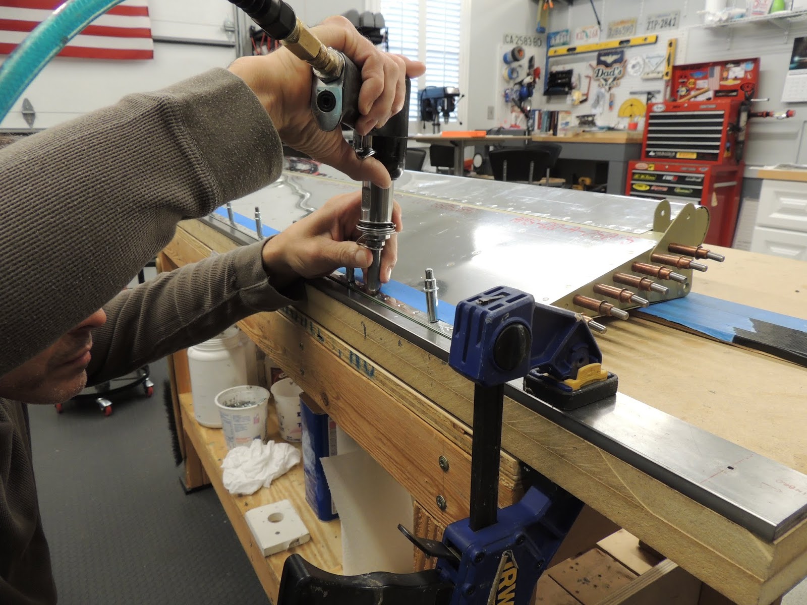
| Because the parts have not been through the priming process yet, I used temporary screws/nuts to attach the pipe to the ribs. The assembly is then placed back in the skins so holes from the leading edge of the skin can be match-drilled into the pipe. To drill the holes into the stainless-steel pipe, I used new #40 bit with cutting oil and battery powered drill. Using a little more force on the drill than used for normal steel and medium speed, the holes weren't as difficult as I expected and turned our good. . Once all the holes were drilled, I stepped up the bit size to #30 for final drilling. Blind rivets will be used layer to fill these hole and further secure the pipe to the leading edge assembly. |
 |
| Neighbor Scott and I reviewing out work after match-drilling the holes in the leading edge. Since we were all set up, we went ahead and brought the right aileron up to the same point as the left. |
 |
| Drilling the holes in the stainless pipe leaves a pretty good burr on the interior side. Probably ok to leave, but here's what we came up with smooth the burrs. Needed two extensions to reach all the holes. |
Oct 18-22, 2018
 |
| Pay close attention to the plans when trimming the aileron stiffeners to size from the piece of stock that comes with the kit. The majority of the time you just need to connect the notches when cutting the pieces to final size. In this case, there is a dimension shown on the plans to cut the stiffeners to the correct length. Even if you miss this dimension, like I did, you would catch the mistake prior to installing the stiffeners to the skins. If not trimmed properly, they would extend into the area where the trailing edge piece will be located. I caught my mistake before installation, but after priming. I had to trim, file, debur, and touch-up prime all 32 stiffeners. Avoid that if possible. |
 |
| Back-riveting the stiffeners to the aileron skins. |
 |
| I did things a little off plans here, so use at own risk. Here's the set-up I used to get the parts assembled enough to drill the trailing edge piece (wedge). |
 |
| To drill the trailing-edge piece, the plans have you cleco install the parts as shown above. However, the plans also have the leading edge skin, to include the counter weight, installed for this process. I left off the leading edge assembly because I found it difficult to keep the whole assembly flat and square on the bench with the clecos attaching the leading edge hanging over the edge. Also, I felt the counter-weight was trying to add a twist to the whole assembly and I was not able to comfortably overcome with weights. Obviously, with my technique, there is no way to have clecos on the lower portion of the assembly. The process seemed to work ok and I got the trailing edge piece drilled. We'll see how things turn out when the aileron is complete. |
 |
| Drilling the trailing edge using wooden block as a guide. 84 degrees is the angle needed to drill perpendicular to the chord line of the trailing edge wedge. |
 |
| Here's the aileron counter-weight attached to the ribs that will hold it in place in the leading edge skin. I used a little shorter stainless screw than provide with the kit. Same grade and stainless, just shorter. I had some thought on how to orient the screw/nut for attaching the counter-balance. I ended up putting the nut on the flange (also added a washer) of the rib as shown here. The nut was very easy to tighten and did not require much holding force on the phillips head using the 90 degree screwdriver. Once the nut was snug, the phillips head seem to "hold' on its own without the screwdriver. |
 |
| The plans advise the use of a hand squeezer with a 1/2" tall set on the shop head side to set the rivets of the nose rib to nose skin. This is due to the curvature of the skin. Without the tall set, the squeezer yoke contacts the skin preventing square contact on the shop head. I didn't have a 1/2" set, so I just added a few washers under the tallest set I had. Something to consider here: Later, the plans discuss avoiding possible twist by ensuring the aileron assembly is level/square when riveting the bottom skins to the spar. They call it "Closing the D-Cell". I followed that advice, but found it very difficult to square the aileron assembly during that process. It seemed the spar was already "set "even before I riveted the bottom skins to the spar. After completing this step on the right aileron, I placed the leading edge assembly, aft side down, on a flat table and noticed a slight twist that I was not able to correct without a bit of force. Even then, it would spring back. It seems the twist here would also carry over to the spar when it gets riveted later during skin attachment. MY THEORY is the D-Cell is actually partially set when setting the nose ribs to the nose skin rivets. Once these are set, it becomes very difficult to "twist" the leading edge assembly by hand. I think it's at this point the aileron twist can be avoided, or at least minimized. I did not figure this out until after building the second aileron so I cannot confirm this procedure. So, long story short: If I were to build ailerons again, I would try and ensure the leading edge skins stayed as square as possible in the cradle while riveting the nose ribs to nose skin rivets. Also, I think I would start setting forward rivets first and work my way aft. I will discuss later, but I did end up with a slight twist on both ailerons. Left is approximately 4/32" and right is approximately 3/32". The trailing edges of both ailerons are perfectly straight as viewed span wise. However, when placed on a flat surface, the twist is apparent. |


October 26-30, 2018
Right Aileron - I built the right aileron using same methods as the left. I will add a few pictures that I did not show during the left aileron construction,....and add a few comments when I get a minute.
 |
| A couple of these slightly over driven, but within the milspec for shop head height. |
Jan 8, 2019
Completed right aileron.
Left and right ailerons complete