Wing Landing Lights (Off Plans) -January 2018
The landing lights for the RV-14 are located on the outboard section of the wing leading edges. The left and right leading edge skins come pre-cut with an oval shaped holes from Vans. There is no requirement to install a landing light and the kit does not include landing lights. However, the kit does provide a mounting bracket the builder installs in the leading edges in case a light is desired. Most builders do in fact install landing lights and Vans does sell an optional landing light kit. The kit consists of a mounting bracket that holds the light and mounts onto the previously installed bracket located inside the wing leading edge. The light provided in the optional kit is a very high quality LED light manufactured by AEROLEDS. However, the main reason I decided to explore alternate landing light ideas was because the light provided in the optional kit is round. I remember when I first saw the RV-14 at an airshow, for some reason, that round landing light in the oval shaped hole in the wing just didn't look right to me. So, when it came time for me to install the landing lights, I ventured off plans in search of something different. Additionally, I wanted to come up with a plan that still used the mounting bracket located inside the leading edge that comes standard with the kit. This would allow me, if things didn't work out, to revert back to the optional landing light kit available from Vans.
I thought this idea/project would be easy enough. However, after the fact, and now that I have completed my "off plans" idea, it did involve a little more time and effort than I expected. I'm happy with the final results, but I will say it was like putting together a puzzle at times. I don't have a good estimate of the time I spent, because it was mostly something I worked on in short breaks in between other building tasks.
 |
| This is the landing light cutout that comes pre-cut from Vans in the left and right wing leading edges. |
 |
| Left wing leading edge (before attachment to wing assembly), showing location of cutout for landing light. |
 |
| I took this picture of a beautiful RV-14 on a ramp somewhere. This shows the look of the landing light as installed using the optional kit available from Vans. The light is a very high quality LED light from AEROLEDS, and while it is probably very functional (and bright), I have never liked the look of the round light in the oval hole. |
 |
| After exploring options for my "off plans" landing light project, I decided on these from Whelen. My plan is to install two per wing. There where several options available, but given the limitations of both my fabrication skills and also my desire to use the plans provided mounting bracket as a base mount (so it can be changed later if desired), these lights looked like a good option. I did an initial test using a battery to check the illumination of these light before I made my final decision to use them. While they are very bright, I think they provide more of "flood" type of illumination than the "spot" type you get when using the round lights. I don't think this will be an issue for me, and will just have to wait and see how they perform once in service. |
 |
| The lights as received from Whelen. The are attached to the backing plate for mounting. I was not able to figure out a way to use the backing plate for my application, so I removed them. |
 |
| Light with backing plate removed. |
 |
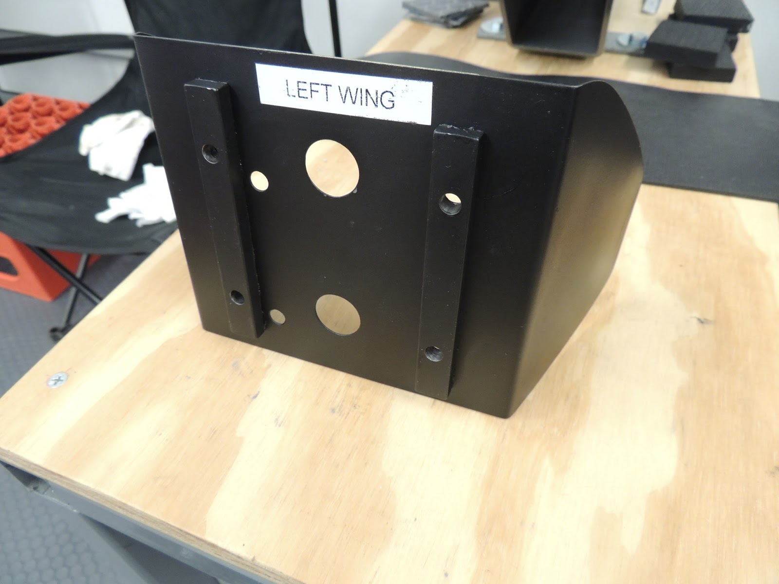
| This is the standard base mount for the landing lights that comes standard with the kit. You will mount this whether or not you plan on mounting a landing light later on. If you decide to use the optional light kit from Vans, there is another bracket assembly that mounts to the bracket shown here. My "off plans" bracket also mounts to this bracket. The only modification I made to this bracket, was the addition of two nutplates. The two located in the center portion of the bracket are standard. I added the two in the upper part of the bracket shown here. There are several holes that come pre-drilled in the bracket for other applications I assume, so I was able to match the new nutplates with two of the existing holes. I did have to drill one additional rivet hole per nutplate. Additionally, one of the existing holes was a little over sized for the #3 rivet used to attach the nutplate. I used an oops rivet in that hole and it worked out nicely. |
 |
| This is the factory supplied bracket mounted in the wing leading edge. |
 |
| To begin the process of my "off plans" landing light project, I needed to bend some metal. I did not have any tools in my inventory to accomplish this, so I got this bending brake from Harbour Freight. |
 |
| I got the 18" brake because it it would fit nicely on the standard RV work benches..., and it was a little cheaper than the larger one (I think around $35). |
 |
| Here's the 18" break mounted to the work bench with clamps. Here, I'm making a bend for the bracket that will mount to the plans supplied bracket previously installed in the wing leading edge. |
 |
| For this bend, I was able to pretty much line up the edge of my aluminum piece with the edge of the break to get the measurement I needed. In this bend, I didn't desire a "crisp" 90 degree bend, but more of a "rounded" bend. I'm not a sheet metal person, so I'm sure there's proper terminology that should be used here:) NOTE: Later during initial installation tests, I found this piece needed trimmed by approx. 1/4 inch. So if I were to bend this again, I would probably only bend 1-3/4" as opposed to the 2' shown here. |
 |
| First bend showing the "rounded" bend. |
 |
| Bracket positioned in the break to bend the opposite side angle. I don't believe I have a picture showing the dimensions of this bracket. However, I do know the back portion of this bracket is the same width/height as the factory bracket that is installed in the leading edge. The side bend dimensions can be determined from the photos above (minus the 1/4" I noted the description). |
 |
| This is the bracket that was fabricated above after holes drilled for nutplates and snap bushing. NOTE: I later enlarged the snap bushing hole to accommodate a larger 2 wire molex plug for 14 awg (factory wire harness wire size to light". |
 |
| Nutplates installed that will be used to mount the reflector and landing light later on. Also shown are the holes drilled on the side "flanges" of this track. These are used to mount this bracket to the previously installed factory bracket. |
 |
| This is my bracket that will mount to the factory bracket previously installed. |
 |
| Here's a picture showing the "upsized" snap bushing I mentioned earlier. |
 |
| With my bracket complete, I now moved on to fabricating a "reflector". The optional kit from Vans (and most other lights I have seen) does not have a reflector. As a result, you are able to see around the light and inside the leading wing leading edge cavity. Most builders paint the inside of the wing cavity black, and that does reduce the visibility of the inside of the wing. However, I though I would attempt to incorporate a reflector with my ides to further reduce the visibility of the wing interior. |
 |
| Her's the basic layout of my reflector design. For size comparison, this is drawn on a standard piece of 8-1/2"x11' paper. The width as seen above is 11". The height, I initially made the same as the base bracket I fabricated earlier. However, after trial fits, I reduced the overall height by approximately 1/4". |
 |
| Reflector after bending side "wings" and drilling holes. the two large holes will accommodate a protruding portion on the back of the light where the wires exit. The two hole to either side of the large holes are for the mounting screws. The two offset holes between the large hole and the mounting holes are for a cooling "port" located on the back of the landing light assembly. |
 |
| Difficult to explain but due to the "puzzle" type process of my landing light project, I needed a space in between my mounting bracket and reflector piece. I used pieces of rectangular aluminum and double-sided taped in place as seen here. |
 |
| Here's my bracket and reflector in place showing the gap that will provide space for the landing light wires. |
 |
| Another piece of my landing light installation puzzle requires the light wires to be connected to a single molex plug. In order to accomplish this, the lights have to be in position as seen here. They will remain "loose" like this until final installation. |
 |
| Here's the aft side of my light reflector. The two lights are on the forward side of the reflector and held in place here temporary screws/nuts. To connect the wires into one plug, I used aviation grade butt-splices. I used different sizes of heat shrink over the butt-spices to provide protection and strain relief for the connection. |
 |
| Lights secured to reflector with temporary screws/nuts during molex plug installation. |
 |
| Lights temporarily installed to reflector with screws that will be used for final installation. |
 |
| Here's the screws I will use for the final installation of my landing lights. Because of limited spacing between the hole in the landing light housing and the clear light lens, I had to look for a screw with a very specific head diameter. These button head socket cap screws worked out well. |
 |
| Here's a view looking into the leading edge cavity from the most outboard rib lightening hole. I used the same wire support idea that is used with the optional Vans lighting kit. Here, my molex plug is seen at the top of the picture. This plug will later be connected to the Vans factory wire harness. I will probably add another bracket to the rib web where the two connectors join to provide support. |
 |
| Interior view of the landing light wires routed through a snap bushing in my fabricated bracket. During final installation, I will tidy these wires up with zip ties or lacing cord. As shown here, my bracket is mounted to the Vans supplied bracket (painted black) using nutplates. I wanted to use the Vans bracket in my "off-plans" landing light idea just in case it didn't work out or, if some time in the future other modifications need to be made. |
 |
| Landing lights installed and ready for testing. |
 |
| To test my landing lights I used this 12v power supply. |
 |
| They work! :) |
 |
| Scott at 35 Ft from wing leading edge. I mentioned earlier the lights I used appear to provide more of a "flood" type of light than a "spot" light. I don't think it will be an issue, and I may even prefer this when in actual use. This is only one wing being tested here. I think when both sides are in operation, I will have plenty of illumination for all my night flying requirements. |
 |
| Scott at 60 Ft from leading edge. |
Overall, I'm happy with my "off-plans" landing light project. It did require a fair amount of trial and error testing and a little more time than I'd planned. Additionally, while I tried to design my light system to allow for maintenance by just removing the landing light lens, somehow during the design process I lost that capability. Due to my reflector and wiring configuration, I may (in certain cases) have to remove the fiberglass wing tips in order to accomplish maintenance or replacement if required. Hopefully, with the LED lights, maintenance will be very minimal.