October 28, 2015
Started the Horizontal Stabilizer today.
De-burred the forward and rear spar, and final drilled a few holes.
 |
| Here's the forward and rear spars for the horizontal stabilizer. I de-burred these using the supplies shown. I just found this flexible sand paper from 3M. It costs a little more but lasts must longer than the paper type. Especially when using it on all the curves and angles of the RV parts. I use the files on the flanges of the spars. There are some small stamp marks that need a couple of passes with the files to smooth out. |
 |
| Using the drill press to final drill the #30 holes of the spar and doubler. |
 |
| Here's the doubler located in the center of the rear spar. |
October 30, 2015
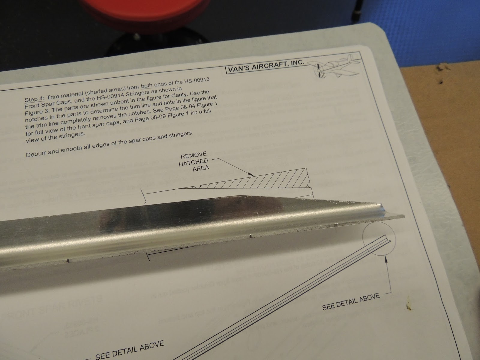
The horizontal spar has four spar caps that need some slight trimming before installation in the front and rear spars.
 |
| Here's the spar cap already cut per the plans. Vans make this fab work pretty easy. The angle has two notches and all that is required is to draw a straight line between the notches and then cut the line. |
 |
| I used the band saw to trim the parts. |
 |
| The belt sander is used to finish up the final trimming on the spar cap. |
 |
| De-burring the spar caps. |
 |
| Spar cap clecoed in place on the spar and "match drilling" several holes between the spar and the spar cap. |
October 31.2015
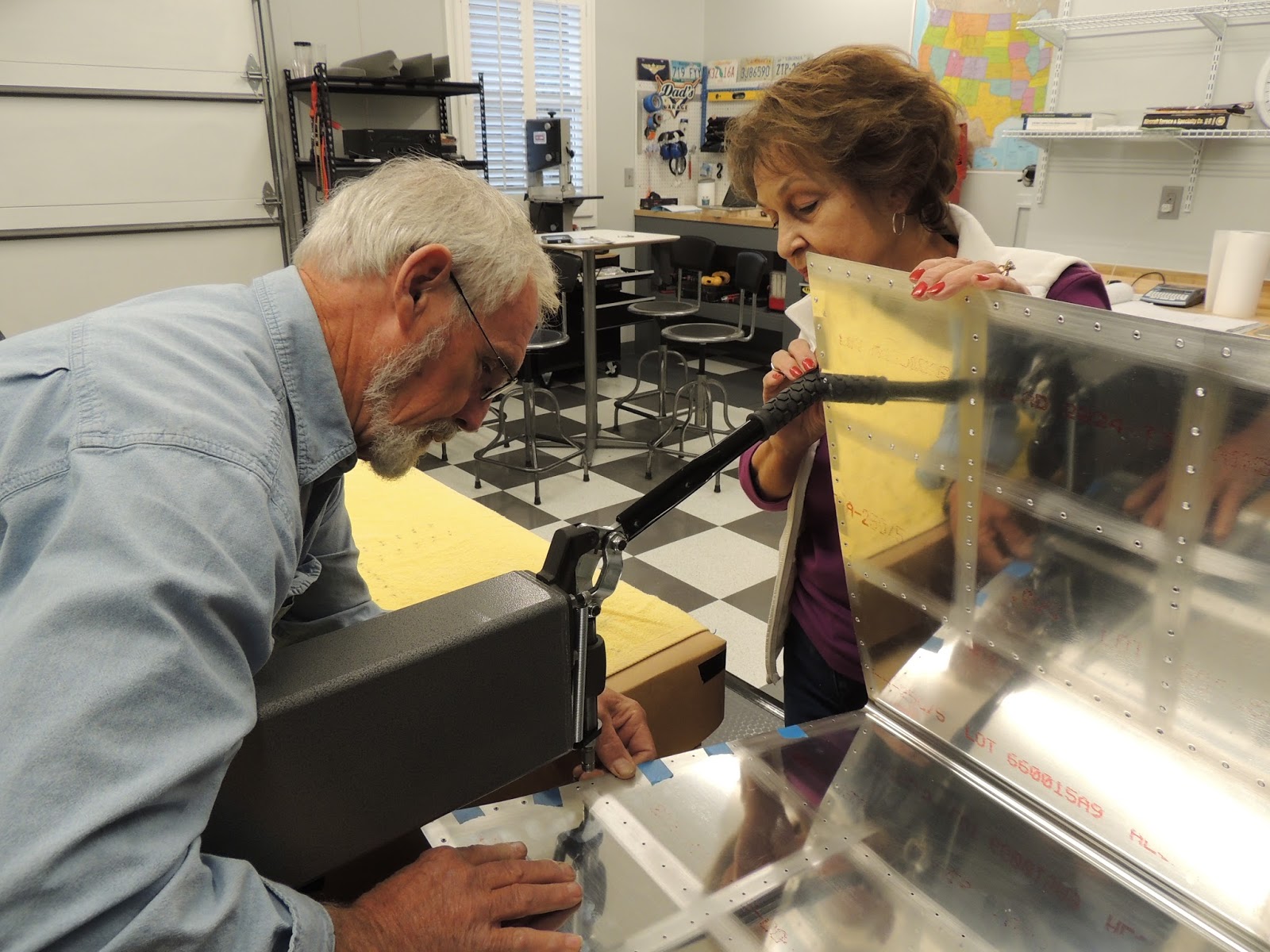
My parents came in town for a visit and were promptly "introduced" to the project.
 |
| Mom got the least fun job peeling the blue plastic off the skins. |
 |
| Here's Dad lining up the dimple dies so Mom can operate the DRDT-2. |
 |
| We were able to get almost all the holes with the DRDT-2. Think there were three in each stab skin that we had to use the C-Frame dimpler to get. These were located in the very forward portions on the skins just next to the curved leading edge. Very easy to get a small smiley on these holes if you're not careful:) |
 |
| Dad made this table for the DRDT-2 to sit on between the two standard EAA tables. |
 |
| I had him make the table longer than the 24" width of the tables. We then mounted the DRDT-2 so that the dies are in the center of the tables. |
 |
The DRDT-2 is mounted aft of center on the table to prevent the table from "riding" up in the back when the lever on the front is pushed down. |
November 2, 2015
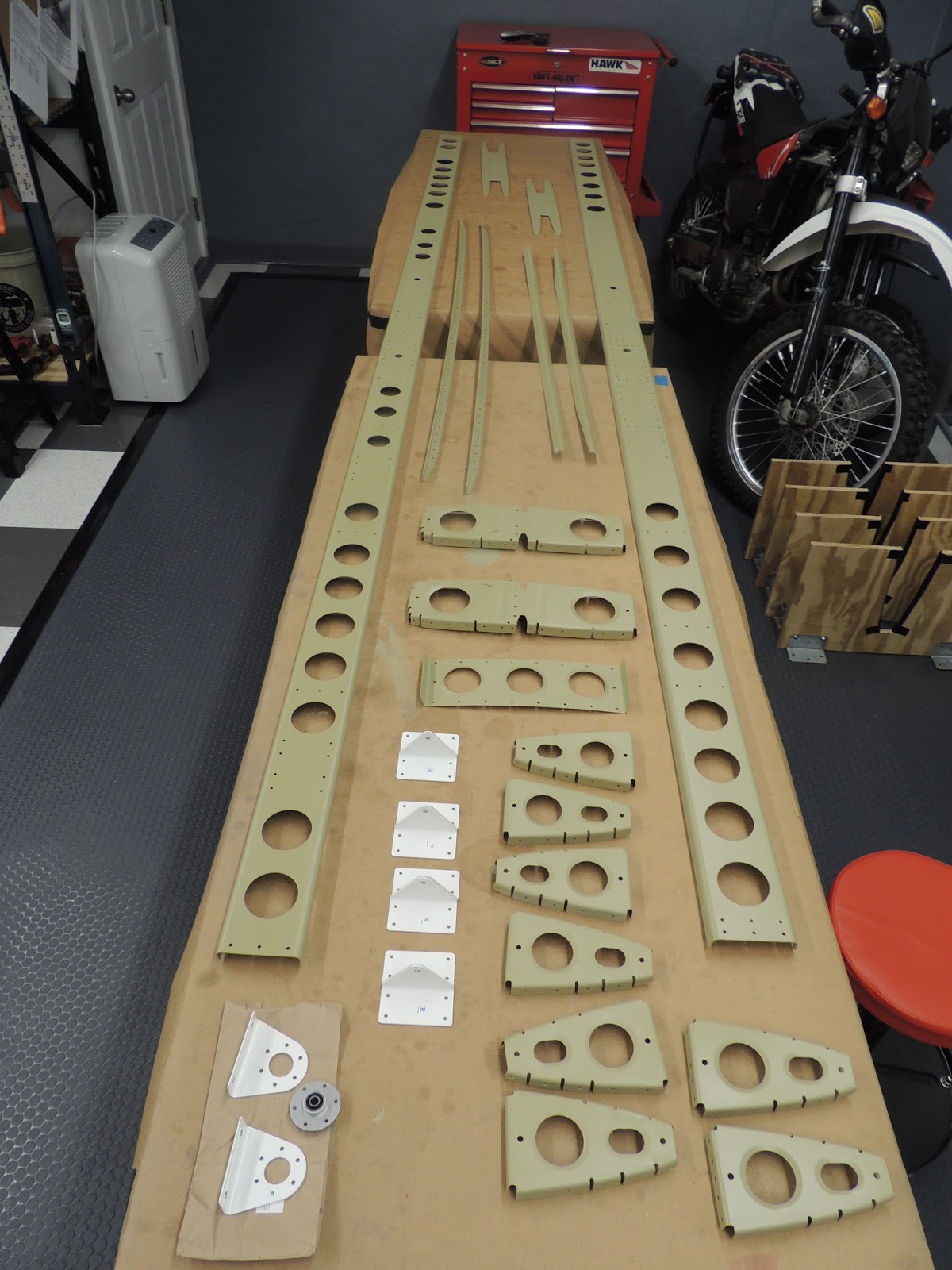
Assembled the parts of the horizontal stabilizer with clecos just to get the "big picture" as to how everything goes together. If I wasn't priming, I could be putting in rivets instead of clecos.
 |
| The horizontal stab is 9.5 ft long. My garage door is just over 8.5 feet wide. I was hoping to get everything but the wings installed before the eventual trip to the airport. I've got a few years before I need to worry about that:) |
 |
| There are over four hundred holes in the spars that need to be mechanically countersunk. There may be a better way, but I'm just using a small variable speed drill with the countersink tool and bit. Due to various factors this tool can be a little tricky to use. It is pretty easy either over or under counter sink without changing the settings on the tool. I get it close and finish up with a debur tool to get the counter sink depth just right. |
 |
| Almost finished with the top side. Now need to flip it over and do the bottom. Plenty of practice for my countersinking skills! |
November 4, 2015
Deburr day.
 |
| Spent several hours deburring the parts of the horizontal stab. As Forrest Gump would say "That's all I have to say about that". :) |
November 24, 2015
After a small setback (see Mistakes page), I finally got the parts for the horizontal stab finished up and ready for priming.
 |
| Here's the parts to the horizontal stabilizer primed and ready to be assembled. |
December 2, 2015
Had some time today to start riveting the parts together for the horizontal stab. Following the plans, we riveted the doubler to the rear spar. These rivets are easily accessible so I decided to use the c-frame to back rivet.
 |
| This is the set up I use for back riveting with the c-frame. In this case, the cupped set for the universal head of the rivet is on the lower part of the c-frame. The shop head of the rivet is formed with the flat set bar placed in the c-frame. The rivet gun is placed on top of the bar to form the shop head of the rivet. I'm discovering that I like to back rivet when possible. It ensures everything is nice and lined up (rivet sets and rivets) which seems to reduce the chances of cutting either the rivet head or the metal surrounding the rivet. |
 |
| This shows the cupped set on the lower portion of the c-frame for the universal factory head of the rivet. |
 |
| Here's a universal head rivet placed in the set. |
 |
| Flat bar in place to form shop head of rivet. |
 |
| Close up of back-riveting set up. |
This is a slow-motion video of back-setting a rivet. Quality not great..shot with phone. Just a test. (Note: It appears in the video the doubler is not sitting flush on the spar. It just appears that way due to the curved radius from the spar web to the flange. The black gorilla tape in the background is attached to vise-grip pliers I used to ensure a tight fit between the doubler and spar while riveting.)
 |
| Neighbor Scott and I back-riveting the doubler to the rear spar of the horizontal stab. |
 |
| Shop head of the rivets on the doubler. This is the forward part of the rear HS spar. This will not be visible once the spar is in place. |
 |
| Factory heads of the rivets attaching the doubler to the rear HS spar. This part of the spar is where the elevator will attach. This part of the spar will be partially visible when the plane is complete. |
December 4, 2015
Today I riveted the elevator hinge attach brackets to the rear spar of the horizontal stab. I was able to back-rivet the rivets for these brackets.
 |
| Here's the elevator hinge brackets clecoed in place. |
 |
| Using the C-Frame to back-rivet the brackets. |
 |
| The rivets all turned out pretty good. Here's the brackets and the factory head of the universal rivets. |
 |
| This is the side of the spar opposite the bracket showing the shop head of the rivets . |
December 9, 2015
Worked on the forward spar of the horizontal stab. This included riveting a doubler and in-spar caps to the spar. Once again, I was able to back-rivet all the rivets for these pieces.
 |
| Neighbor Scott and I back-riveting a doubler to the forward spar of the horizontal stab. |
 |
| This is a spar cap that is riveted to the inside flange/web of the forward spar of the horizontal spar. |
 |
| My wife came out to take a few pictures while we were riveting. She suggested we wear the hearing protection that was sitting on a shelf just a couple feet away. Not a bad idea:) |
 |
| Here's the doubler riveted to the forward spar of the horizontal stab. This part of the spar will be facing forward. |
 |
| Here's the opposite side of the spar showing the shop heads of the rivets. The upper and lower in-spar caps can also be seen. |
December 10, 2015
Continued working on the horizontal stabilizer components. The next step in the plans is the assembly/riveting of the stringer web assembly. Had to brush up on using the hand and pneumatic squeezer for the rivets on these parts. No back-riveting here:)
 |
| This is the stringer web assembly which is located in the center section of the horizontal stab. Not too many parts and rivets are easily accessible for hand and pneumatic squeezers. |
 |
| The pneumatic rivet squeezer does a nice job with the rivets in this location. I did set a couple of practice rivets on scrap material before the real thing. This gave me a chance to set the right amount of "squeeze" to achieve a proper shop head on the rivets. I'm still very cautious using this tool. When you pull the trigger, something is getting squeezed or dimpled. |
 |
| Stringer web assembly complete. |
December 12, 2015
Today I continued work on the horizontal stab assembly by riveting the ribs to the forward spar. I accomplished this initially using a rivet gun and bucking bar. The rivets turned out well, however, I was not able to get a nice tight fit between the rib flange and the spar. There was an approximately. .004 gap. While this would probably be perfectly acceptable, I wanted a tighter fit. Initially, I didn't think I would be able to use the pneumatic squeezer due to the rivet locations. However, after looking through my friend Marks selection of squeezer yokes, I found a combination that would work. Also, I was able to change the orientation of the rivet and put the manufactured head on the rib side instead of the spar as I did the first time. This would help pull the rib tight to the spar. (more on my rivet removal procedure on the mistakes page)
 |
| Here's the squeezer and yoke combos I used to squeeze the rivets on the ribs to spar. |
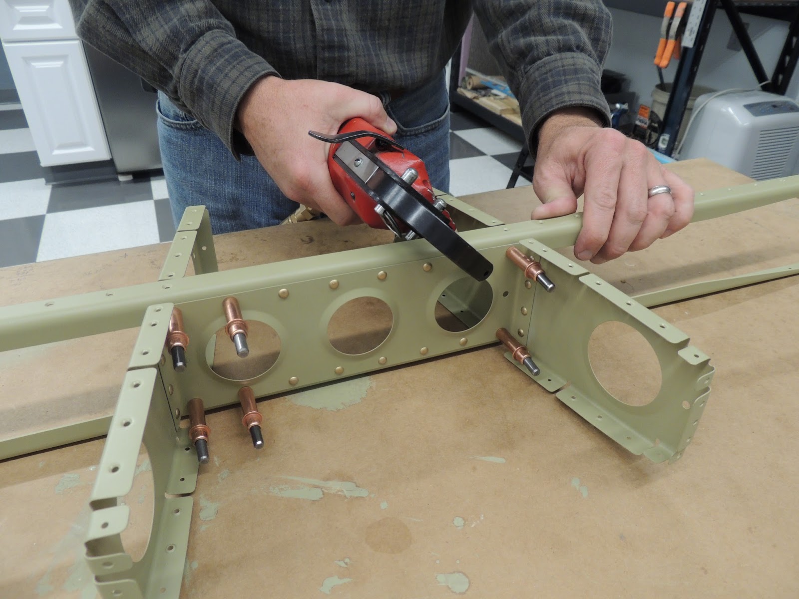
Today I assembled and riveted together the flange bearing to its brackets so that it can be bolted to the rear spar of the HS. I also clecoed the HS leading edge ribs in place in the left and right stab skins. I was able to rivet the outboard ribs, but will need help to rivet the inboard ones.
 |
| The plans advise to mount the flange bearing brackets to a flat surface prior to riveting. I used a leftover wood post base base that I had. |
 |
| When setting these rivets, I partially set every other rivet using a hand squeezer. I then put the remaining rivets in from the other side and partially set those. Finished off with pneumatics squeezer. |
Next, I moved on to the leading edge ribs in the HS skins.
 |
| Here's the HS skins in the cradles that I build per the plans. |
 |
| The nose ribs are clecoed in place. To rivet, I was able to get to the closer rib from the end of the skin. The further rib, I will need to access for the top. |
 |
| Here's how I riveted the outboard nose rib. I will probably need help with the inboard rib..especially the rivet in the most forward hole. It's pretty tight due to the curvature of the leading edge skin, |
 |
| Here's the outboard rib after riveting. |
 |
| This is the exterior view of the rivets for that outboard rib. |
December 16, 2015
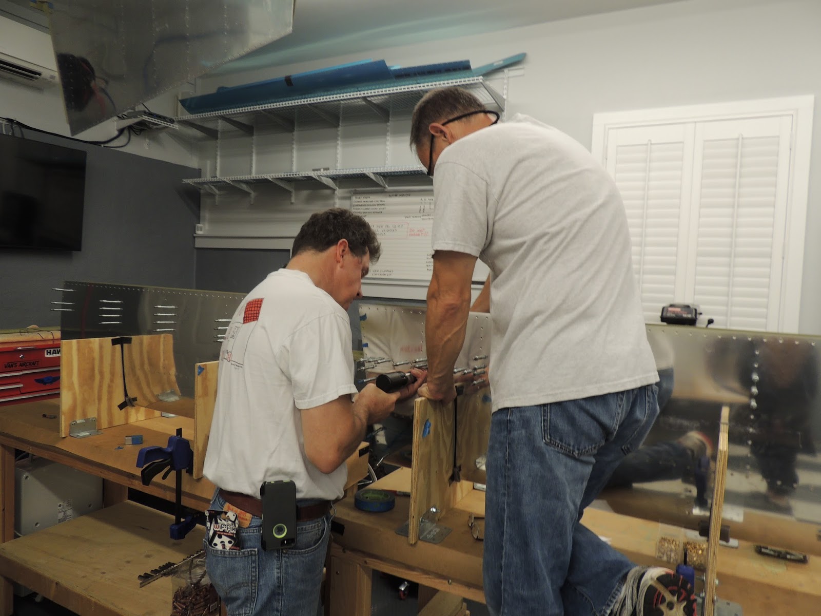
I've worked off and on a little bit over the Christmas holiday riveting the skins to the horizontal stab assembly. Most can be done solo, but definitely easier to have a helper.
 |
| Neighbor Scott and I riveting the skins to the horizontal stab assembly. |
 |
| Almost all of these rivets are set using a pneumatic rivet gun and bucking bar. A few around the edges can be set wit the hand or pneumatic squeezer. |
December 31, 2015
Finished up the rivets in the skin of the horizontal stab. Also had ten universal head rivets to set that attach two inboard ribs to the forward spar. The plans are a little vague as to when these are to be riveted. May have been a little easier to access these rivets before the skins were in place. However, using an off-set rivet set and bucking bar, we were able to set the rivets with good success.
 |
| Neighbor Scott and I discussing our options for setting the ten rivets or the forward/inboard ribs. |
 |
| Here's one side of the stab showing five of the ten rivets that need to be set. The cleco with blue tape is in place for a skin rivet. I just wanted to wait to put this rivet in to allow easier access to the spar rivetes. The ribs in this area are at an angle and prevent us from using a squeezer or a straight rivet set with pneumatic rivet gun. These are #4 size universal head rivets with lengths of -7 and -8. |
 |
| We used the off-set rivet set and tungsten bucking bar with angled head to set these rivets. We were VERY careful setting these rivets and practiced on some scrap material first. If we messed these up, they would not be easy to drill out and replace. |
 |
| Here's the tungsten bucking bar with the angled end that we used. |
 |
| Here's the bottom view showing the angled head bucking bar we used to form the shop head for these rivets. We got lucky, and all rivets turned out great! |
 |
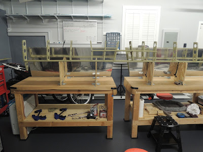
| No more clecos on the horizontal stab. Not quite finished though. I still need to attach the rear spar to the trailing edge of this assembly. Shouldn't be too bad. There are a few blind rivets to set for the spar to rib connection and the skin to spar flange rivets to set using the squeezer. |
January 9, 2016
Today we finished the horizontal stabilizer! This included riveting the rear spar to the stab ribs and skins. Neighbor Scott and his dad Richard stopped by help drive/squeeze rivets.
 |
| This is the rear spar for the horizontal stabilizer. |
 |
| Scott and I placing the spar in the HS assembly. |
 |
| Blind rivets are used to attach the spar to the ribs. I was able to use RV builder friend Mark's pneumatic rivet puller for the center of the three blind rivets. Due to limited clearance because of the spar flange, we used the hand puller for the outboard rivets. |
 |
| I'm using the hand blind-rivet puller to set the two outboard rivets. |
 |
| Scott and his dad are using the pneumatic squeezer to set the rivets that attach the skin to the spar flange. |
 |
| Better view using showing Scott setting rivets with the pneumatic squeezer. |
 |
| My turn to keep my rivet squeezing qualification current:) |
 |
| Richard and I finishing up the squeezed rivets. Richard is a long time aviation enthusiast and is very mechanically inclined and learns fast! He is welcome to stop by and help anytime! |
 |
| The completed Horizontal Stabilizer! Ready to hang on the wall until needed a few years from now:) |