January 12, 2018
Today we started building the fuel tanks. The RV fuel tanks are considered a "wet wing" design meaning the fuel is stored in the wing structure cavity. In the case of the RV14, and most other RVs, the fuel tanks are basically another wing leading edge section as we previously completed. However, for the fuel tank sections, all the areas where pieces are joined together will be sealed with a special fuel tank sealant to prevent fuel from escaping. This "wet wing" design is used by many aircraft manufacturers including everything from small piston airplanes to commercial and business jets. On aircraft that don't use the wet wing, one alternative is a fuel bag system. However, the fuel bag adds weight, typically needs a large open area to be installed, and can be difficult to repair in the event of a leak. The wet wing system, while maybe a little more painstaking to build, is a pretty simple idea and overall a good way to store fuel,
There are a few manufacturers that produce the sealant used, but it seems like most RV builders go with the Flamemaster product. Here's some details I cut and pasted from the internet: " Flamemaster MC-236-B2 integral fuel tank sealant is a two-part polysulfide base compound which cures at room temperature to a flexible, resilient rubber with excellent adhesion to aluminum, magnesium, titanium, steel, and numerous other materials. It is designed to withstand the attack of sulfur compounds that are present in jet fuels, and aviation gasoline"
The sealant needs to be mixed at a specific ratio (10:1) to produce the proper curing/sealing properties. It can be very messy to work with and doesn't smell very good. There are several "techniques" that builders when working with this sealant during fuel tank construction. Each builder must research as best they can and decide which technique to use. I am still in the research stage and haven't quite made a final decision on that yet.
Typically, every time you start a new section of the build, there is a fair amount of material preparation that needs to be done before you can actually start building This is true for the fuel tanks as well. Nothing very difficult, just a bunch of small tasks.
 |
| Here's most of the rib sections for the fuel tanks. |
 |
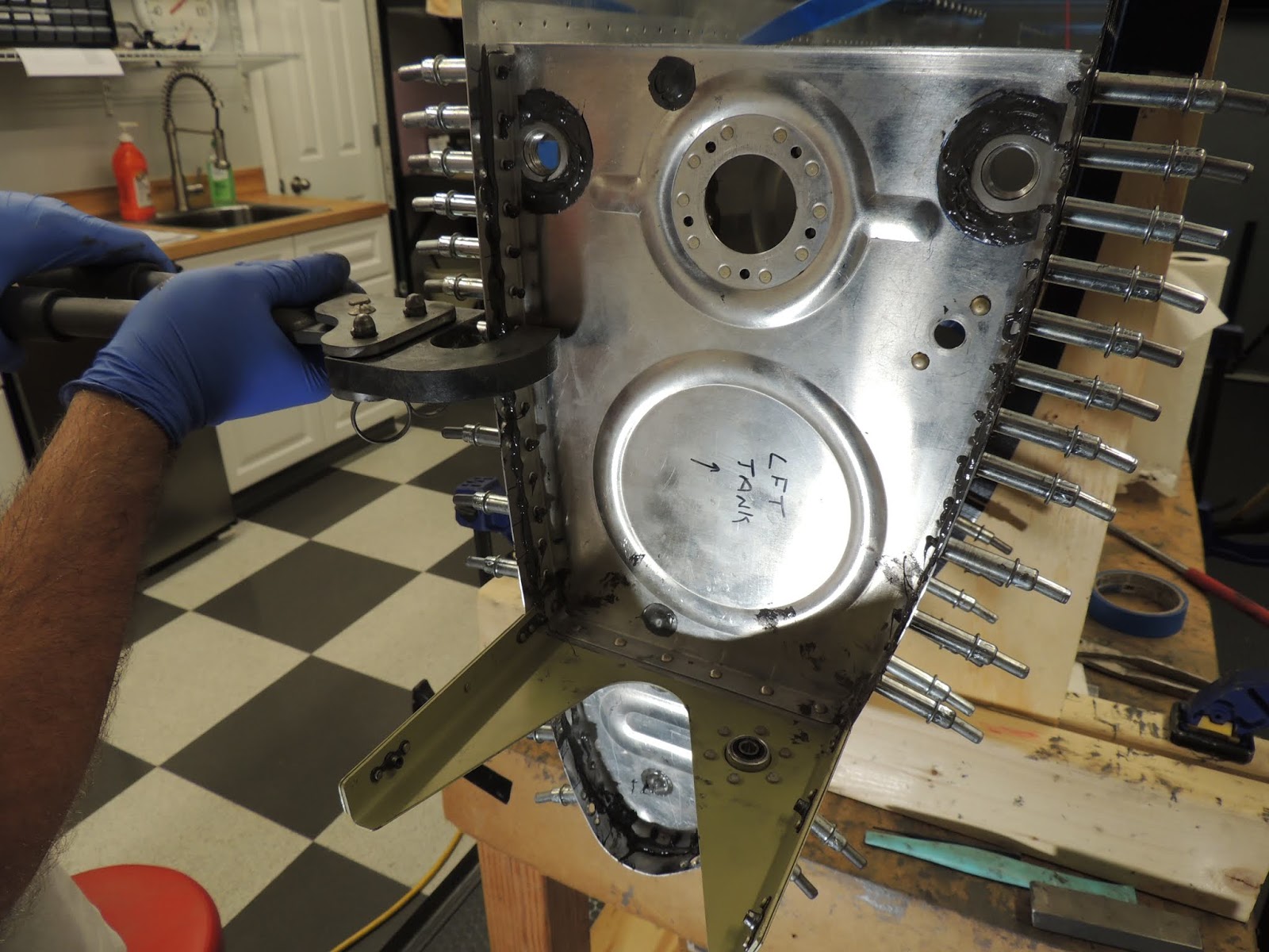
| This is the most inboard fuel tank rib. The two flanges seen here (clecoed in place), will be riveted to the aft ends of these ribs. The one located on the bottom of the rib will be used for the fuel pickup line. The hole for this flange comes predrilled in the rib from Vans. The second flange is located on the upper portion of the rib and is used, according to the Vans tech support guy I talked with, to "futurize" your aircraft. It will be used as a fuel return line that will be required for certain types of engine/configurations. This flange is not required to be installed and the hole in the rib does not come predrilled. The "normal" engine recommended by Vans does not require a fuel return line. However, not knowing what new developments may be made regarding engine design, I decide to "futurize" and add the fuel return flange. It will be plugged if I decide not to add additional fuel return plumbing at this time. |
 |
| Some of the prep work I mentioned earlier involves cutting fuel tank skin stiffeners. They come in a long piece of material that needs to be cut into pieces. The long material has notches that indicate where cuts will be made. All you have to do is draw a line to connect the notches and then cut the lines. Here Scott uses the band saw to make the cuts. |
 |
| For some cuts, Scott used a piece of wood to support the material while cutting the tank skin stiffeners. |
 |
| Minus the skins, here's most of the structural parts that will make up the left and right fuel tanks. The stiffeners that Scott cut can be seen in the foreground of the picture. The parts here are in various stages of deburring, final-drilling, match-drilling, fluting, etc. This is all the behind the scenes stuff that can take lots of time and yet look like very little progress. |
January 16-17, 2018
 |
| Here's the "Z-Brackets". They come form Vans in one piece of material and need to be separated by the builder. They make it easy by providing notched areas where the cuts need to be made. Before separating into individual pieces though, the plans have you countersink some holes for nutplates. The Z-Brackets will eventually be attached on the aft side of the fuel tank to the baffle. The nutplates on these Z-brackets will then be used for bolts that secure the fuel tanks to the wing spar. |
 |
| Z-Brackets with rivet holes for nutplates machine countersunk. |
 |
| Next, the Z-Brackets are separated into individual pieces using the bandsaw. |
January 20-24, 2018
 |
| I used the belt sander to dress up the edges of the tank stiffeners that were cut earlier on the band saw. |
 |
| Rough edge of tank stiffener from bandsaw cuts that needs to be smoothed out. |
 |
| Angled edge of thank stiffener also needs smoothed where it was cut with band saw. |
 |
| I previously de-burred all edges and holes for the fuel tank ribs. However, before dimpling, I needed to give the rib flanges a good scuffing where the proseal will be used to create a seal between the rib flange and the tank skin (fay sealing). The scuffing provides a good "tooth" for the tank sealant (proseal, flame master, etc.) l to grab. |
 |
| Here you can see the scuffed rib flange surface. Just before tank sealant application I will give another light scuff with scotchbrite pad and wipe clean with MEK. |
 |
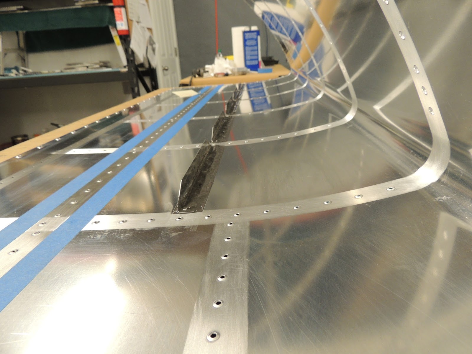
| Above, I scuffed the faying surfaces of the fuel tank ribs in preparation for the fuel tank sealant. Here, I also scuff the areas of the fuel tank skins were stiffeners and ribs will be located. I used blue tape to mark the areas that will be scuffed. |
 |
| More blue tape applied to mark the areas to be scuffed for the tank stiffeners. You can see in the picture the areas that have already been scuffed for the fuel tank ribs. |
 |
| The blue sharpie line indicates the fuel tank rib and stiffener widths. I wanted to have a little extra scuffed areas on each side of the ribs and stiffeners to allow for a fillet of tank sealant compound. To keep things simple, I made the scuffed areas one inch wide. Using the 32" scale, I placed the 16/32" mark on the rivet holes to lay out the 1" wide strip for scuffing. |
 |
| I did a test assembly the left tank components here for a couple of reasons. First, was to just a get a good feel for how things would go together without the worry of having the tank sealant compound to deal with. Also, the plans have you install the rear baffle so the rivet holes in the skins that attach the baffle can be machine countersunk. Installing the baffle gives the pilot point of the countersink bit a good guide hole which, in turn, makes for a nicer countersunk hole on the skin. Without the "guide hole", the countersink bit has a tendency to wander, and chatter which could lead to a sloppy countersunk hole. There is much debate on the builder blogs as to why these holes are countersunk vs. dimpled. It does appear the dimpled proponents have a good case and I almost went that route. However, the designers at Vans have done a few more RV builds than I have, so I decided to follow the plans recommendation. |
 |
| Machine countersinking the holes in the skin for rivets that will attach the fuel baffle. |
 |
| I have never had good luck using the countersink cage. I set it, countersink a few holes perfectly then, for some reason, I get a hole that's too deep or too shallow. I spend more time constantly checking and resetting than countersinking. So..,I just use the countersink bit with no cage. Seems scary at first but after a few countersinks I get a pretty good rhythm going, and can usually get very close after the first trigger pull. The second trigger pull will normally get the exact depth I'm looking for. About 1 out of 10, I will get the depth perfect on the first trigger pull. Very rarely do I go too deep. |
 |
| Since the baffle was temporarily installed, I took the opportunity to check the fit of the Z-Brackets. The Z-Brackets are attached to the rear baffle, and interior tank rib flanges using blind rivets. The aft side of the Z-bracket will have nutplates that will allow the tank to be bolted to the main wing spar. |
 |
| Here, I'm using the edge breaking wheel to put a slight bend in the aft edge of the tank skin. This helps for a more flush fit and smooth transition to the adjacent wing skins when the tanks are installed on the wings. I always have to put sticky notes on these edges to remind me to accomplish this task prior to dimpling the holes in the skins. I heard it's very difficult to do after dimpling:) |
January 28-30, 2018
The majority of the parts for the fuel tanks do not get primed. This includes all interior surfaces that will be in contact with fuel, and areas where tank sealant compound will be applied. However, since I was having withdrawal symptoms from priming, something was getting turned green!:) Since my wife's car was not available, I thought I'd stick to fuel tank pieces. There are a few parts on the external potion of the tank that could be primed, so they got the primer treatment.
 |
| The two large pieces in the center are tank attach brackets. The portions taped off with blue tape will be inside the tank and do not get primed. The Z-Brackets will get primed everywhere except the surface that will make contact with the fuel baffle. I debated on that for awhile as I wasn't sure if I would apply tank sealant to that faying surface or not. While I feel it shouldn't be required, I decided that I will apply a very thin layer of sealant to those surfaces. I applied blue tape to those areas to keep them primer free. |
 |
| Primed tank parts. |
Once the above pieces were primed there's some dimpling, and a few nutplates, bearings, and spacers installed.
 |
| Scott using the hand squeezer to set the rivet on the flange bearing that is mounted to the tank support bracket. |
 |
| Tank attach bracket with bearing installed. The bearing will support one end of the aileron torque tube with the other end supported by a bearing on the main wing structure. |
 |
| Tank attach bracket. I will scuff the area marked where the inboard ribs will be sealed and riveted. |
 |
| There are shims attached to the upper and lower flanges of the attach brackets. These shims, located on the exterior of the tank, will allow a narrow piece access skin to sit on top of the other wing skins. These narrow skins will allow access to the wing root and the electrical and fuel fittings located there. I had to read the plans a few times to make sure I got the dimpling correct for these shims. |
 |
| Shim located on the lower side of the tank attach bracket. Note no dimpling or countersinking. Apparently that gets done later. |
 |
| The most inboard tank rib is two separate ribs..fwd and aft. These two rib sections will be joined together as shown above by the tank attach bracket. I temporarily assembled the tank attach bracket and the forward and aft inboard ribs to develop a riveting plan for later. Easier now than when the tank sealant is in place. It does appear there will be one "problem child" rivet. The top rivet of the rib flange could be tough..especially with the bearing installed. I think we have a plan though and will see how it works out. |
 |
| Inboard tank ribs and attach bracket |
 |
| This is the aft rib of the two piece inboard tank rib set. There are a some nutplates and fuel flanges that need installed before this rib gets installed later. |
 |
| The blue fitting shown here is for the fuel vent line. It is not installed at this point. I'm just checking for fit with the anti-rotation plate that is installed now. Checking for fit paid off. One fitting fit nicely in the anti-rotation plate, however, the fitting for the other tank did not. I had to file a small amount of the anti-rotation plate to get the blue fitting to fit and seat nicely. If I had not have caught this now, it would a problem to fix later once the anti-rotation plate was riveted and sealed in place. |
 |
| Test fitting fuel tank vent fitting with anti-rotation plate. |
 |
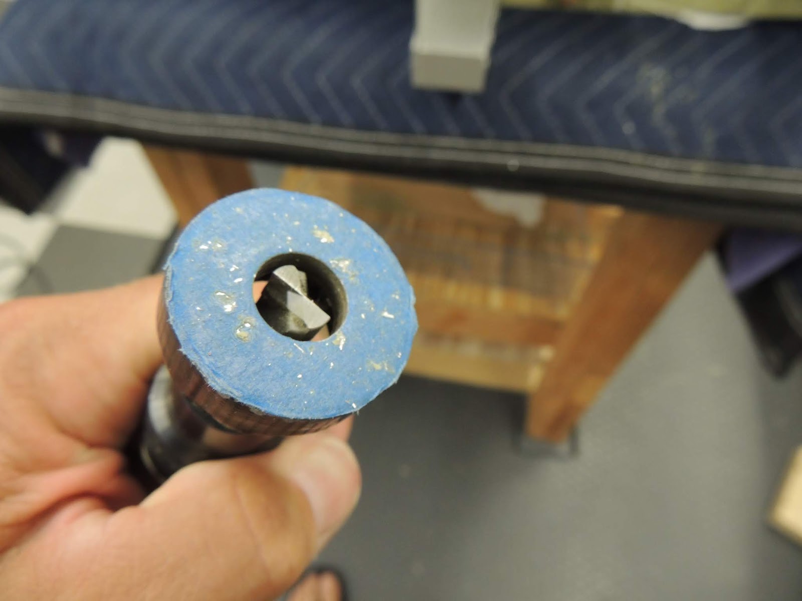
| There are a few tooling holes in the inboard and outboard fuel tank ribs that need sealed. The kit provides #6 rivets to fill these holes. The plans state these rivets do no need to be fully set and just need to be "swelled" enough to seal the hole. i don't remember the length of the #6 rivets supplied with the kit, but I felt they were longer than required for filling a hole. I cut these rivets using my rivet cutter. Not sure the length I cut them. I just placed them in the rivet cutter as shown without using any of the spacers on the cutter. |
 |
| Here's one of the #6 rivets, after cutting to a shorter length, in one of the tooling holes. |
 |
| To lightly set these #6 rivets, I used the C-Frame. Luckily, I was able to rummage through my loaned bucket of tools from friend Mark and come up with a #6 rivet set. |
 |
| Using C-Frame to set the rivet in the one of the tooling holes of the onboard tank rib. |
 |
| #6 rivet set just enough to swell and fill the tooling hole. |
 |
| The most inboard tank rib is divided into two pieces (fwd/aft sections). The two pieces are joined during installation at the fuel tanks attach bracket. This picture show nutplates being attached to the aft rib section. These nutplates will be used later to secure the Fuel Level Sender unit. |
 |
| Inboard/Aft fuel tank rib with nutplates installed for Fuel Level Sending Unit. Also seen here is one of the #6 rivets used to fill a tooling hole. Rivet will later be covered with tank sealant. |
February 1, 2018
Time has come for my first use of the tank sealant (Flamemaster brand) on the fuel tanks. The inboard/aft ribs for the left and right tanks have two fuel line flanges and an anti-rotation plate for the vent line that need sealing. NOTE: WE WILL NOT BE WINNING THE AWARD FOR THE LEAST AMOUNT OF TANK SEALANT USED!:)
 |
| Here, I'm using the semco gun to apply sealant to one of the fuel line flanges. I could have used a tongue depressor and acid brush to spread the sealant here, but I just wanted to get some practice using the semco gun. |
 |
| I trimmed the bristles of the acid brushes to better spread the tank sealant. |
 |
| Spreading tank sealant with trimmed acid brush. |
 |
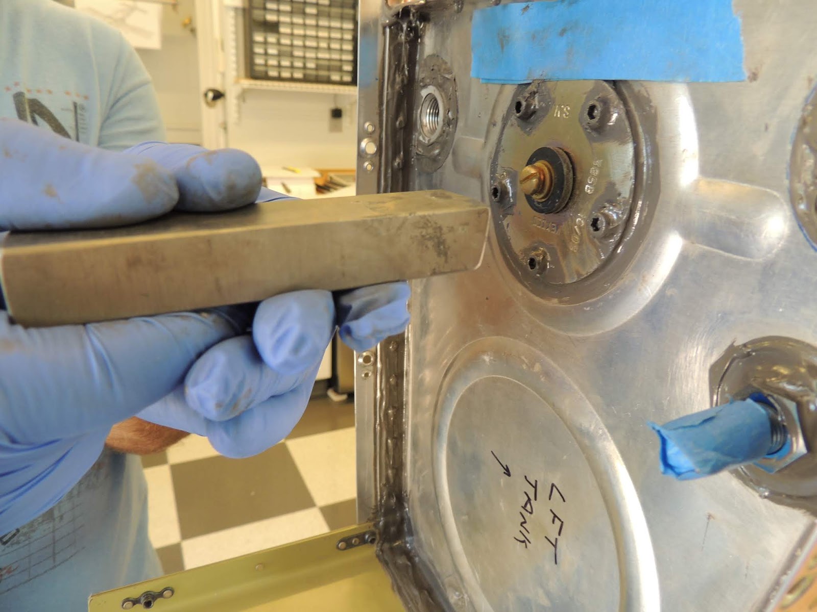
| Applying sealant to the lower fuel line flange. This is the flange were the main fuel supply line will connect. The top flange will only be used if you choose a fuel/ignition//engine configuration that requires a fuel return line. If not, the flange will be closed off with a plug. I have not decide for sure what configuration I will use. |
 |
| Applying sealant to the lower fuel line flange. |
 |
| To attach the fuel flanges to the ribs, I used the C-Frame. Because of limited space on the flange, I found to get the rivet set to fit squarely on the shop head of the rivet I needed to modify the set as shown. ` |
 |
| Fuel flanges, vent line anti-rotation plate and "fill" rivets all sealed up on the inboard fuel tank rib. This side of the rib will be on fuel side of the tank. |
 |
| Inboard fuel tank rib for the right fuel tank, This side of the rib will be the outside, or non-fuel side of the tank. The empty hole in the rib is where the fuel level sending unit will be attached. |
February 5-6, 2018
Next step in fuel tank construction is installing stiffeners to the lower portion of the tank skins.
 |
| The tank sealant "prep table". When dealing with the tank sealant, I've found it helps to be organized and have a plan in place. do a dry run of the steps you will be completing just to make sure you have everything you need and ready to go. There's no need to be rushed once the sealant is mixed. If mixed properly, I've found about two hours to be a good limit before I see signs of the sealant beginning to slightly set. This time is also dependent on variables such as temp, humidity, etc, so your results may vary. We are doing this during cooler outside temps, and keeping the shop a little cooler. |
 |
This picture shows the flamemaster tank sealant in the back ground. This is the quart kit that I purchased from Vans. The sealing compound is the quart container and the accelerator is the smaller black container with the white top. The sealing compound and accelerator are mixed by weight at a ratio of 10:1. Also seen here, a glass bowl containing the rivets we will be using soaking in MEK to clean any contaminants.
|
 |
| Here's the scale I use to weigh the tank sealant for mixing. I use a scrap piece of aluminum as a mixing plate. Here, the scale shows the mixing plate weighs 60g. |
 |
| To zeroize the scale with the plate in place, this scale has a Tare button that can be used. |
 |
| Here we add 60g of sealant compound to the mixing plate. |
 |
| Using the 10:1 ratio required, we add an additional 6g of accelerator to mix bringing the total weight to 66g. |
 |
| Once the proper ratios have been added the two compounds are thoroughly mixed. Here, we're using a plastic putty knife to mix on the mixing plate. However, we found the plastic putty to be difficult to clean, and for subsequent mixes we used metal blade putty knife. Cleaning the mixing plate is pretty easy by using the putty knife to scrape the plate almost clean and then wipe with mek. The sealant can also be left to cure on the mixing utensils and then peeled away, but it takes additional time to allow the sealant to cure. |
 |
| This is the used semi gun I purchased from Brown Tool: Secco Gun Kit . While not required, I read from other builders the semco gun can make the process a little easier and less messy. The kit contains the used gun and 2.5 oz cartridges with 1/8" nozzles. The sealant is mixed and then loaded in the cartridge . The plunger (black pice at end of clear cartridge )is installed, and the cartridge is placed in the metal tube of the semco gun. The metal tube is attached to the gun trigger mechanism and air pressure is used to "push" the black plunger inside the cartridge. It supplies a very slow, controlled flow of sealant. We found 25 psi air pressure worked good for us. |
 |
| Using the semco gun to apply tank sealant to a skin stiffener. |
 |
| Here's the stiffener after the sealant has been spread evenly using a tongue depressor. |
 |
| The process most builders use to attache he skin stiffeners to the tank skins is back-riveting. Here, we have the rivets for the stiffeners taped in place with rivet tape. |
 |
| The stiffeners are placed in position over the previously installed rivets, and a back-rivet set is then used to set the rivets. |
 |
Once all the rivets were set, we covered the shop heads of the rivets with sealant. I believe most builders only use a dolyp of sealant on each individual shop head. However, I decided to put a complete layer of sealant over the shop heads and stiffener flanges. Definitely more sealant required, but I had the idea that the increased surface area of sealant to flange would give a better grip. I had already scuffed the entire flange area of the stiffer anyway, so applying a continuous bead of sealant wasn't any trouble, and may even be simpler than applying the dolyp to each individual rivet head.
|
 |
| Once the sealant was applied to the shop heads using the semco gun, I used an acid brush with the brushes trimmed to evenly spread the sealant. Note: Most builders just cover the shop head of the rivet with a "dollop" of sealant as is standard practice. However, because I had already scuffed the upper and lower surfaces of the stiffener ribs, it was just easier to cover the entire rivet shop head line with sealant. |
 |
| Sealant spread on all areas of the stiffener. The area between the stiffeners needs to be free of sealant for installation of ribs later on. |
 |
| Removing tape after sealant application. |
 |
| The Semco cartridges and nozzles are easily cleaned and can be re-used. I found it best to leave the sealant as is after use (i.e. don't wipe off excess), and allow to completely set up. The sealant is then easily peeled away. Even the nozzles, as shown here, are easily cleaned and re-used. However, depending on how fast you work with the sealant it's nice to have a few extra cartridges/nozzles to use while the used ones are setting up for the cleaning process.. |
February 12-13, 2018
Install fuel drain flanges and fuel cap flanges.
 |
| This is the fuel tank filler flange that is supplied with the kit. It is anodized red aluminum. I don't have a picture, but the lip of this flange is tapered to allow for a nice fit with the curved skin. You just have to be sure to orient the flange properly during installation. |
 |
| In order for the flange to fit the dimpled skins, the rivet holes of the flange must be machine countersunk. I used a piece of scrap aluminum the same thickness as the tank skin to check countersink depths. |
 |
| We coated the mating surfaces of the fuel drain flange and tank skins with sealant and used a squeezer to set the rivets. |
 |
| Inside tank view of the sealed shop heads of the fuel drain flange. |
 |
| Fuel drain flange installed. Later, a fitting will be installed that will allow fuel to be drained from the low point of the tank. Normally, only a small sample of fuel is taken to check for contamination; water, debris, etc. |
 |
| We decided to back-rivet the rivets that attach the fuel tank filler flange. Here, the rivets are taped in place prior to placing skin on back-rivet plate. |
 |
| Inside tank view of rivets that will attach fuel tank filler flange. |
 |
| We coated the mating surfaces of the filler flange and tank skin with sealant prior to placing in position. You can see the back-rivet plate sticking out from under the skin. We used cardboard strips to support the tank skins to match the height of the back-rivet set. When setting these rivets, we slightly set a rivet, then skipped a couple and slightly set the next. We continued until all rivets were slightly set and then final set all rivets using the same pattern. Not sure this technique made a difference, but it seemed like the same logic as tightening the lug nuts on a wheel. |
 |
| Sealant applied to the rivet shop heads of the filler flange. Again, no awards here for the most sparing use of sealant. Instead go just covering the ship heads, we covered the whole thing. Probably overkill, but my thought was the more surface area the sealant has to "grab" the more likely it will stay put. |
 |
| Inside tank view of fuel filler flange installed and sealed. |
 |
| Exterior view of fuel filler flange. |
February 25, 2018
Today we installed the first rib of the left fuel tank. I had read a lot of information and different processes builders use to accomplish the rib installation for the fuel tanks.
The process many builders use to install ribs is as follows; Apply tank sealant to the ribs/skins, place rib in position and cleco every hole. This is the point where builder techniques tend to differ a bit. Some will apply sealant, install, and cleco every rib in place. They will then let the sealant cure for a length of time (some overnight, and some days/weeks later.) before returning to install and set the rivets. This process has it's advantages. First, it seems to be less messy! With all the ribs installed and curing, you are under no rush to rivet. You are able to rivet at your convenience when you get the time. After riveting is complete the builders using this process, again at their convenience, cover the shop heads of the rivets with sealant.
Another process builders use (and the one I chose) is "wet riveting" the tank ribs. Using this process, sealant is applied only to as many ribs as you feel you can rivet while the sealant is wet. The rib/ribs are installed, clecoed, and riveted all in one session. The shop heads of the rivets are then covered with a dollop or layer of sealant as desired.
I chose the "wet rivet" method for a couple of reasons. I liked fact that there is no "cold joints" of tank sealant. Everything from the sealant squeeze out in the dimple, to the covering of the shop heads is one simultaneous curing of sealant. There is no doubt this method is messier and probably more time consuming, but it works for me so I'm going to "stick" with it:)
Builders have had good success using both methods I discussed above and, like many areas of the project, you research as best you can and pick a process that works for you.
 |
| This is the left fuel tank placed in the cradle and ready for our first run at sealing and riveting a rib. The plans sequence of events have you start with the inboard rib and work outboard. We followed that order except one point. The most inboard rib is divided into two pieces (shown in picture with light sitting on it). The plans have you begin with this small inboard "half rib", and work outboard. However, we've learned from previous experience it's a good idea that, when all the pieces are pre-assembled with clecos, to develop a rivet setting plan to help identify any potential problem rivets. This is especially true for the fuel tanks since sealant will be involved, and you may not have the luxury of time to come up with a plan of attack. In the case of the most inboard rib, we noticed one rivet that could be a little difficult to set. It is one of the #4 universal heads that will attach the two inboard "half ribs" together. We think we have a good plan for that rivet, and I'll discuss and show pictures later. |
 |
| Left tank in cradles ready first rib installation. |
 |
| Scott uses the semco gun to apply the sealant to the rib. |
 |
| Once the sealant is applied, a tongue depressor is used to spread the sealant evenly on the rib flange. |
 |
| We also decided to apply a layer of sealant to the area of the skin where the rib will be placed. Probably overkill here, but my though was that when inserting the rib into the skin, there may be a possibility the sealant could be "scraped" off the rib flange in certain areas. By applying to skin as well, I was comfortable all areas would have a layer of sealant. This is probably a good time to mention that I don't think we will be winning the award for " Most Conservative Tank Sealant Use". Sealant is relatively inexpensive, and I want to be comfortable when the day comes to close everything up that I've sealed the tank as best I could. Once again, I'm sure are there are thousands of RVs flying with leak free tanks that used half the sealant I will. It's another one of those builder experience/preference areas. |
 |
| Rib inserted into the skins with clecos installed in every hole. As many builders have discovered, these ribs can sometimes be difficult to install and get the rivet holes to align. Neighbor Scott made an observation during our trial runs that due to the configuration of the "slots" in the flange, it may be easier to begin the cleco alignment process with the bottom flange first. We've had good results by inserting one cleco about mid-section of the lower flange just to get things lined up. We then move to the most forward holes and continue cleco insertion. We still need to use a small punch occasionally to "find" the hole, but no real force required to get the alignment required. Additionally, it also seems that when the sealant is applied, the rib is even easier to maneuver into position. Although with the sealant, it is a little more difficult to see the holes, so it's a tradeoff. |
 |
| Non-flange side of the rib showing some sealant squeeze out that I will later form into a nice fillet seal. |
 |
Post riveting of the first rib with shop heads covered with a layer of sealant. Like I mentioned earlier, I'm not using the sealant sparingly. Instead of a dollop of sealant on each individual shop head, I decided to just layer the whole flange with sealant. My thought was the increased surface area for the sealant to "grab" might increase long term adhesion performance...and, I believe it's actually easier than putting a dollop on each rivets shop head. Again builder choice/preference here. You can see from the picture that working with the sealant can be a messy process. This was our first rib and we hoped to improve our process as we moved along. However, at the time of writing this we have six ribs installed and, while our process has improved, we still end up with a rib that looks similar to the one shown here. As I read from one of the other builders blogs: "sometimes the proseal just gets angry".:)
|
 |
| Rib after some careful cleaning with MEK. |
 |
| Non-Flange side of rib fillet seal along the edge. I just used sealant that squeezed out and an acid brush with trimmed bristles to form the fillet seal. |
March 9-11, 2018
Fuel Tank rib installation continues. We are working both tanks simultaneously and so far we've got four out of 14 installed . Right now our process has been to install one rib on one tank per session, and then switch to other tank the next session. We are still tweaking our process, but right now each rib, including final scuffing/MEK wiping, sealant mixing, riveting, an occasional drilled out rivet, and cleanup is averaging about two hours. However, as we progress, I think we will shave a few minutes off that time.
Just an observation so far on the tank sealing process. It's not as bad as I was expecting. I'd read all the terrible things about it and was not looking forward to it at all. I think it was because of that expectation, that I'm finding it not to be that bad...and, in a weird way, a little enjoyable:) I may be weird, but I don't even think the sealant smells that bad!. However, with that said, it still is a slow, repetitive, stressful part of the project, and I'm not jumping out of bed every morning excited to mix up another batch of sealant:)....although, I think I'd take tank sealing over deburring any day!
Like I mentioned earlier, we are wet riveting the ribs. We are not applying sealant to all the ribs, clecoing in place and letting the sealant set up for a length of time. Our process is: Apply sealant to rib flange and the tank skin, install the rib, cleco every hole, start at the forward lower rivet and begin riveting aft every other rivet. About halfway aft, we switch to the top skin and repeat the process. We alternate top and bottom until all rivets are installed. I will say that I believe the wet riveting may be a little more difficult. It is a little more messy, altough we are getting better, and probably a little more difficult to rivet. The sealant can make the rivet shop head slippery which makes bucking bar control a little more challenging. However, after a few rivets, it's not that big a deal. We do try and wipe the excess sealant off the shop head of the rivet, and the bucking bar, before riveting as much as possible and that seems to help.
Not much new to show as we progress with the fuel tank ribs. Here's a couple of pictures showing the tank sealant that oozes out after the ribs are placed in the skins and before clecoing.
 |
| Tank sealant that oozes out of rivet holes before clecos are installed. There is is still a good amount of sealant in the dimple when we remove the cleco and insert a rivet. We are not allowing the sealant to setup as many builders choose. We are riveting while the sealant is wet. During riveting, there is a fair amount of sealant that gets squeezed out from under the rivet head. However, there still appears to be sealant in areas where the rivet head and dimple don't seat perfectly. |
 |
| The view inside the tank skin after rib is inserted with sealant and before clecos are installed. You can see a piece of cardboard in the leading edge of the skin to help protect in case of a dropped bucking bar. I saw this on another builders site and though it was a good idea. |
March 13-17, 2018
Work continues on fuel tank rib installation. Neighbor Scott and I have settled into the one rib a day routine. Probably could do two/day, but one keeps everything nice and relaxed. We have been working both tanks simultaneously by installing a rib on one tank, setting aside and working the other tank the next session. We have been averaging about two hours/rib. That time begins with sealant mixing and ends at cleanup. I have seen builders that rivet these ribs solo, so I know it can be done. However, the rivets on the forward (curved) part of the skin are much easier with a riveting partner. We have been pretty consistent with our "bad" rivets per rib, averaging about 3 rivets that "club" over. Sometimes, it can be difficult to get the bucking bar angle just right due to the curvature of the skin and the glare of our lighting off the shiny skin. Also, even though we try and keep the shop head of the rivet clean of wet sealant before bucking it still may be "slippery" enough to allow the bucking bar to move slightly during bucking. I realize 3 or 4 bad rivets per rib is probably not a terrible thing, and sometimes you're better off not replacing, but so far we have had good luck with the replacement process. When replacing rivets we have learned, so far in our build experience, that the quality of the replacement depends a lot on whether or not the dimple was damaged by either the "bad" rivet or the removal process. Once the dimple or hole is damaged the success of the replacement rivet decreases greatly. I think we have had good luck with out tank replacement rivets due to the dimples and holes remaining in good condition. However, just to be safe, when installing the replacement rivet, I have been putting a very slight "pre-squeeze" on the properly sized 3.5 rivet using the hand squeezer. This makes the rivet fit very snug in the hole/dimple, and also the slightly reduced rivet height further increase the chances of a nice set while still meeting the shop head dimension requirements.
 |
| This is the right wing tank. We have been installing ribs from inboard to outboard. Here, we have the fourth inboard rib (not counting the most inboard rib), in position for riveting. We position the cradles between the two work benches so we have easy access to the rivets on the leading edge portion of the tank. In this picture the rib is installed with tank sealant with a cleco in every hole. |
 |
| Typically, we begin riveting on the lower side of the tank skin at the forward edge and work aft a few rivets and then switch to the top side. Here is the forward part of the top skin showing four set rivets with the fifth covered in tape ready for bucking. Also, you can see the most forward rivet circled in red labeled "mby". That is our process for possible candidate for replacement. We continue riveting until all rivets are set and then return to the red circles to determine the final verdict. |
 |
| Right tank with the fourth inboard rib installed. One more interior rib on this tank to go before we move to the j-channel, vent line, and finally installing the inboard and outboard ribs. |
RV production slowed over the past couple months due to some unscheduled home maintenance and several other "to do" items I have been slacking on. I think other builders may agree that once you start the RV building process, other projects seem to get moved to the back burner. Easy to see how that happens. Airplane building...even de-burring, is more fun than renovating/remodeling the laundry room:)
Back to RV production. Fuel Tank; J-Channel, Vent Line and Outboard tank ribs.
A few of the following steps were conducted in a different order than listed in the plans. Where we deviate from the plans, we always do a few practice runs, and try and consider all possible risk/benefits. A couple things I recall where we went off plans regarding fuel tanks include, delayed installation of outboard tank rib. We thought it made working with the vent line a little easier. Additionally, we assembled the inboard fwd/aft ribs and attach bracket as one unit and before placing in tank skins. There are a few driven rivets that attach these three parts together that we felt were easier to set before placing ion the tank assembly.
J-Channel installation,..........
Fuel Tank Vent Line installation............
Fuel Tank Outboard Rib Installation.....
 |
| Be careful not to place tank sealant much past the edge of rib flange of the outer ribs. To much sealant, and the skin from the leading edge assembly will not be able "nest" properly over these dimples. |
May 11, 2018
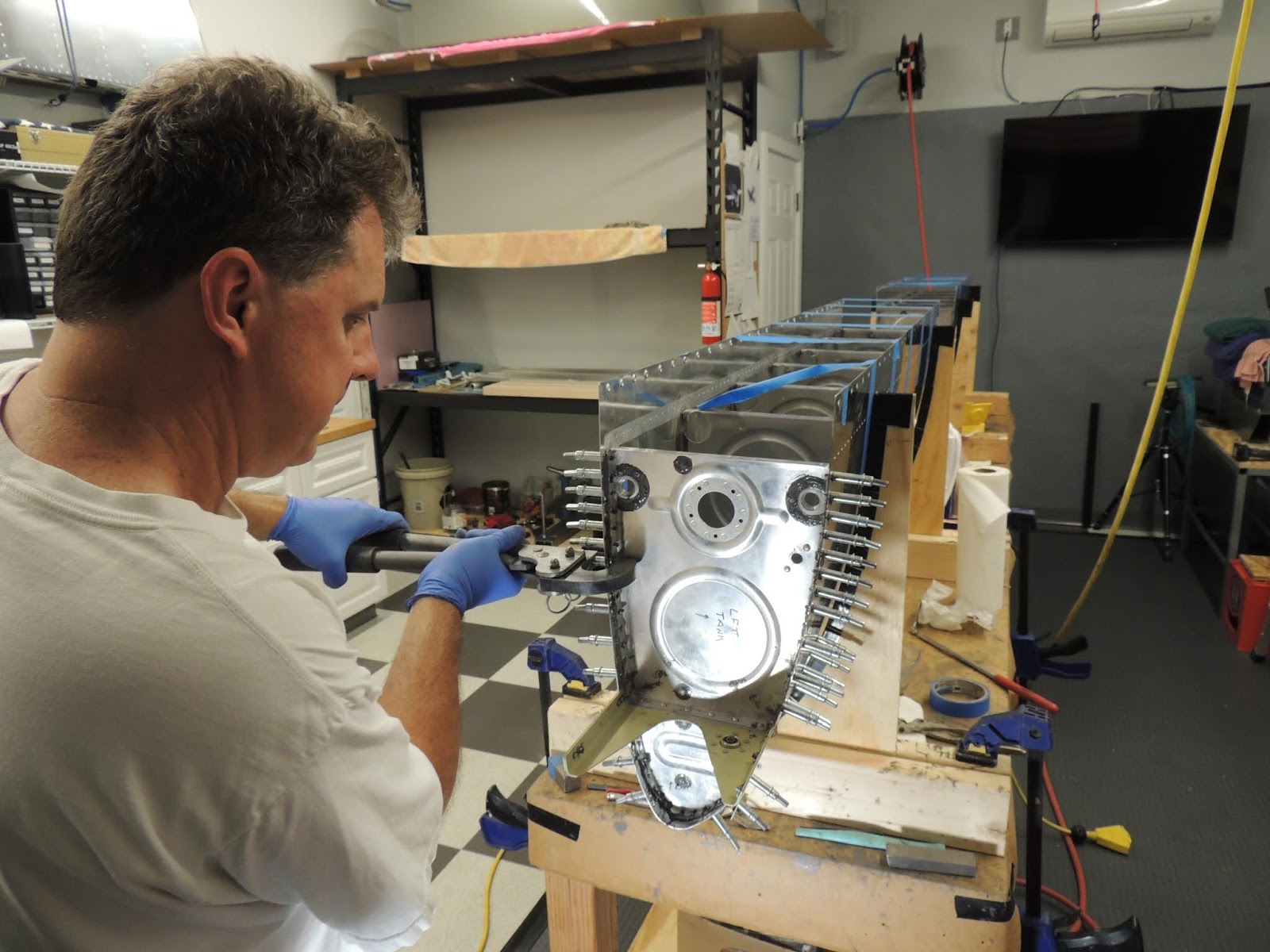
Fuel Tank Inboard Rib Assembly. This is one of the areas we deviated from the sequence of the plans steps. We assembled and riveted the three parts of the inboard rib assembly prior to installing on the tank skins. There are six universal head rivets that attach the small fwd rib, the attach bracket, and the aft rib together. After some practice runs using the plans sequence, we felt these rivets would be easier to set before the assembly was installed. A couple things we found include; with the assembly installed, you are unable to "push" the aft rib inboard slightly due to the j-channel to allow the use if a straight rivet set. We would have to use an offset rivet set to set the six rivets, and that combined with limited bucking bar options due to obstructions, we did not like the odds of setting nice rivets. With the unit outside the tank assembly, we were able to slightly push the rib out of the way and use a straight rivet set. It worked out great. However, using this method, it is slightly more difficult to apply tank sealant to certain areas when installing the assembly. The inside areas of the small fwd rib, and the fwd edge of the attach bracket are slightly more difficult to access. However, with prior planning (and generous use of sealant), we are comfortable that we were able to get good coverage of these areas. Again, this is an area personal preference. Many builders have stuck to the plans and had great results as well.
 |
| This procedure is not per the plans, but it worked good for me. We secured the tank attach bracket to the work bench as shown in the following pictures. |
 |
| With the tank attach bracket secured to the work bench we then clecoed the forward and aft ribs (using tank sealant where needed), to the assembly. |
 |
| Using a long straight rivet set and small tungsten bucking bar we were able to set the six universal head rivets fairly easily. |
 |
| The upper rivet is the most difficult of the six due to the angle of the skin/bracket and the bearing. We again used the small bucking bar with an angled end to set this rivet. Luckily the rivet set very nicely. This was the rivet that had me a little worried and the reason we did several trial runs using different methods. Also, the main reason we went off plans and assembled the three pieces on the work bench instead of in the tank assembly. I don't like using the offset rivet set which would have been required using the plans. Here, we were able to move the aft rib slightly out of the way and use the straight rivet set. |
May 22, 2018
Fuel Tank Inboard Rib Installation: Note: The following pictures show the procedure we used for the inboard rib assembly for the fuel tanks. This is not per the plans. See description above for out reasoning.
 |
| Applying tank sealant to inboard rib assembly. This was one of the areas where our off plans procedure was a little more difficult. Ensuring we had good sealant coverage to the forward rib and attach bracket took some extra care. |
 |
| Again, we probably over applied tank sealant. We do get a lot of squeeze out and make quite a mess. However, particularly for these inboard ribs, we want to ensure good coverage. The curved portion of the forward rib appears to be an area that has leak potential if not sealed properly. |
 |
| Here, Scott uses hand squeezer to set the rivets for the inboard rib assembly. |
 |
| Inboard rib assembly installed and sealant cleaned up. |
June/July 2018
Ok. The following step is probably totally unnecessary and will provide no benefit all....I did it anyway:) I've read numerous accounts
(VAF Link) of builders that have experienced paint blisters over rivet heads after final painting. There are many theories as to why the blisters occur. One has to do with fuel/fumes/pressure somehow migrating through the tank sealant and making its way to the rivet head, which is covered with paint, forming a paint blister.
My theory, just a guess and not proven at all, is that somehow the fuel/fumes/pressure somehow makes its way to the dimple/rivet head. Builders are not seeing/reporting these blisters while flying the plane prior to final painting because there's no paint to form the blisters. The leaks are sometimes not visible prior to painting because it may just be pressure from fumes exiting around the rivet heads, or such a small amount of fuel that it doesn't leave a blue stain. I wondered if builders that paint their planes prior to flying (or putting fuel in the tanks) experienced the paint blister phenomenon. My thought on this isI wonder if the fuel/fumes/pressure were already present in the rivet head cavity for the builders flying unpainted. When the planes get final paint, the fuel/fumes/pressure gets trapped in the cavity and will form a blister under certain conditions. I realize almost builders do seal the rivet dimples with sealant before setting the rivets. Is it possible though there may still be a very small air cavity after setting the rivet.
So, my thought was to try and fill any of these microscopic air gaps in the rivet dimple with primer. I'm using AKZO primer and, from my experience, once it cures it does not give up easily. My process was to coat the rivet line with the Akzo primer. I applied with a stiff bristle brush making sure to dab the brush over the rivet heads. I then used a rag to wipe away the excess akzo from the tank skins. After the akzo was final cured, I cleaned the skins with acetone.
Again, I have no idea if this process has any benefit at all. However, it was very easy to do and can't see how it could have any negative consequences. I could be wrong. Additionally, I think if I could paint the tanks prior to flying (filling with fuel) I would do it. However, that may not be possible.
 |
| Dabbing the AKZO primer along the rivet lines. |
 |
| I quickly wipe away the primer from the skin surface. Hopefully, the remaining primer will fill any voids in the rivet/skin dimple. |
Fuel Tank Sender Installation
 |
| Washer configuration NOT per plans. The plans recommend leaving a 1/32 " "gap"" between the fuel sender and tank rib. This gap will enable some type of thin blade to be inserted between sender and the rib to cut the bond of sealant if removal is ever required. I wondered how I would know when to stop tightening the screws in order to leave the 1/32" gap. I decided to use washers as shown above to ensure an even gap was maintained. Additionally, because the electrical ground for the fuel sender is made through the sender assembly to the tank skins, somehow there needs to be good metal/metal contact between the sender assembly and the tank skins. The plans advise to place a washer under the head of one of the screws used to secure the sender to the rib. This washer should help maintain a good electrical ground connection through the sealant compound. I actually did not use the washer under the screw head as advised by the plans. I felt the screw head "grinding" into the sender plate as it is tightened would be sufficient for a ground. If I ever have fuel indication issues due to grounding, I'll know I should have followed the plans. |

 |
| This picture is from the Vans parts catalog. You can see there are two separate fuel sending units, left and right. Make sure to use the correct unit for the proper tank. Under the description, you can see the range of resistance is 20-240 ohms. They indicate the empty value is approximately 240 ohms and full is 20 ohms. You will notice in my pictures below that my "full" resistance was approximately 31 ohms and "empty" was approximately 249 ohms. |
 |
| Right Tank - full resistance. |
 |
| Right Tank - empty resistance. |
 |
| Left Tank - empty resistance. |
 |
| Left Tank - full resistance. |
": |
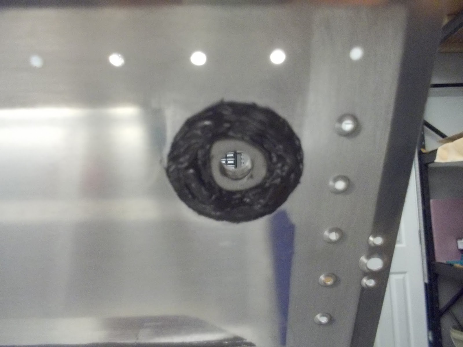
| The connection point of the float wire and the fuel sending unit is a plastic piece with two small clips. The float wire is held in position by these two small clips. It seemed like a weak point to me, so I added a small blob of tank sealant at the connection point. |
Left Tank Baffle installation.
Initially, the tank baffle installation process looks like a fairly easy task, and it is. However, there are many small tasks required that end up taking quite a bit of time. We are using the wet riveting process so it makes for a pretty long work session. I chose the wet rivet method for a couple reasons and, because I have a skilled helper the process goes fairly smoothly. However, even with the two of us working together, the baffle installation process took about five hours...per tank. We may just be slow:) Using this method, everything from parts clean to final rivet is completed in one session. Some builders use a method where they apply sealant and install the parts with clecos only. They let the sealant set for a period of time and then return to do the riveting. That method still requires a good amount of time, just spread out over a few sessions. That method has advantages and disadvantages, just like wet riveting does, but may be a better choice if working solo.
Our process starts with Scott mixing the sealant. He mixes two separate batches. When mixing larger batches, it's easier to get the proper ratio and a thorough mix of the two parts. When working the left tank, we mixed two batches of 100g each. This turned out to be a little more than required, and we had some left over. So, for the right tank we found that 150g was about right for us. Again, we're not going to win any awards for minimal proseal use.
While Scott mixes the sealant, I get the parts final prepped by scuffing and mek wipe down. Scott then places first 100g of sealant in the semco cartrige. I use the semco gun to apply the sealant to the areas required. I use an acid brush with bristles cut short to evenly spread the sealant. The plans give recommendations on where/how much sealant to use. The problem of too much sealant on the mating surfaces could cause the tank to "grow" which may lead to fit problems when it comes time to mount the tank to the wing structure. We probably used a "bit" more sealant than the plans recommended. However, I was careful to spread it thin and evenly in areas I felt may cause fit problems later. Hopefully everything will fit together nicely. We'll find out later when we mount the tanks.


 |
| VERY thin layer of tank sealant. More later. |
July 8-9, 2018
Getting very close to finishing up the left tank. Just need to let the sealant cure for several days. We will then set the few remaining rivets that were left open per the plans. Then the fun part.., the leak check!
 |
| Left tank VERY close to completion. Sealant is curing here. The few clecos seen here are the rivet holes that were left open per the plans. Once the sealant cures, we will install these rivets. |
 |
| Aft view of left tank showing the baffle and attached Z-Brackets. To continue my SOP for covering the entire rivet line with sealant, I covered the heads of the blind rivets that attach the z-brackets to the baffle, and aft-flanges of interior ribs. |
 |
| You'll notice here we did not put sealant of the shop heads of the rivets that attach the baffle to the skins. In theory, if sealed properly, fuel should never get to this point. Additionally, we noticed that there will be minimal clearance between several of the inboard rivets and the wing spar later during tank installation. Rather than risk clearance issues the sealant may cause, we decided to go without. Given our "very liberal" use of sealant to date in the fuel tank build process, this was a tough decision! I wanted so bad to mix up another 60g and go to town on those shop heads:) |
 |
| Sealant curing! |
July 17, 2018
Left Fuel Tank Leak Test
After allowing the tank sealant to cure for ten days, it was time for the moment of truth! We prepped the left lank for leak testing using the Vans leak test kit. The kit consists of a cap, plug, and schrader valve, (required balloon sold separately). The basic principle of the leak test is; seal off all openings in the tank, fill the tank with air, and then spray the tank with soapy water, and look for bubbles.
 |
| There are a couple different options as to how to connect the apparatus for the ballon leak test. The plans give one method, and the leak test kit from vans give another. I can possibly see why the plans have you place things differently than the leak test kit instructions. I decided to use the method described in the leak test kit. The ballon gets connected to the vent line using some type of clamp. Initially, I used a small spring type clamp. However, during the bubble test, the clamp leaked and we switched to a worm-screw clamp. I didn't want to damage the threads of the vent line fitting, and I thought it might help the seal, so I added a couple of wraps of rubber tape tom the threads. |
 |
| Here's the ballon attached to the vent line using the worm-screw clamp. I have a picture further down that shows the spring type clamp that I initially used. |
 |
| Tank moved outside for the bubble leak test. Note the red ballon used for the left tank. Any guesses what color we used for the right tank??:) |
 |
| This picture shows the spring type clamp I initially used to secure the balloon to the vent line fitting. You can see the bubbles indicating a leak. I replaced this clamp with a worm-screw type clamp and it did not leak. |
July 21, 2018
Funny Story...NOT
Well, after successful leak testing of the left fuel tank, neighbor Scott and I coordinated our schedules and planned a day to close out the right tank by installing the baffle.
Interesting situation occurred during our right tank baffle installation. Funny now (not really), but certainly no laughing the day this happened. We had everything set up and ready to go. Scott begins with the sealant mixing while I finish final parts prepping (scuffing, mek wiping, etc).
Everything was going very smoothly, and we had just applied all the sealant to all the areas required. We placed the baffle in position and installed all clecos. At this point, we took a short break. During the break, I was returning the two proseal containers to the refrigerator where we store them. In the refrigerator, I also have a sealant kit that my friend Mark gave me when I first started my RV project. We used this sealant for some miscellaneous things early in the build. Anyway, I noticed the can that was already in the fridge was a lot cleaner than the can we had just used. This is where I heard
this in my head. I realized we had used the old sealant that was expired by about two years! Initial thoughts were all over the place as Scott and I discussed the situation. Finally though, we both agreed we could never sleep well again if we left the old sealant on the tank. So began the process of disassembly, sealant removal, and hours and hours of cleaning. You think proseal is messy during installation....that's nothing compared to this:( We finally got all parts back to original condition and. at the end of the day, we felt good that we made the right decision. We will now have to coordinate our schedules once again and give it a second try.
To be continued:)
July 28, 2018
Right Tank Baffle Install
Today we closed up the right tank by installing the baffle. With the experience we had from the left baffle, and our previous attempt on the right baffle, the process went very smoothly.
August 6, 2018
After letting the tank sealant for the baffle cure for seven days, it was time for the leak test.
 |
| Right tank moved outside for the bubble leak test. |
 |
| Not shown, but once again we used a spray bottle filled with dawn dishwashing liquid and water to spray the tank. We were not shy spraying the tank with the bubble mixture. We completely saturated all areas by positioning the tank as necessary to get good coverage. |
 |
| After bubble testing and sitting on the bench for a couple of days the green ballon is still inflated. I think that's a good thing:) |
Update Jan 2019 - I decided to hold off installing the tanks on the wing structure for a while and move on to other things..flaps, ailerons, etc. During that break, I decided to do a couple things to the tanks before installing them. First, I decided to apply tank sealant to the exterior portion of the baffle flange along the shop head rivet side. Theoretically, fuel should never make it to this area, but I decide to do it anyway. The other thing I decided to do before installing the tanks was to shave the manufactured heads of the rivets that attach the baffle. I countersunk the skins for these rivets per the plans, however they ended up slightly proud after final installation. This seems to be a fairly regular occurrence and there are a few theories as to why. One theory is the tank sealant between the skin and the rivet head makes the rivet sit slightly proud. I suppose this could be a factor, but since I squeezed my rivets with the sealant wet, I would think this would not much of an issue. Whatever the case, most of my rivets ended up slightly proud. The options are to leave them alone...possibly the painter will sand the heads down slightly. Some builders use a rivet shaver to shave the rivet heads slightly. Some remove the rivets, and re-countersink the skins. I ended up doing something a little different. I will explain in the pictures below, but I basically used a small palm-sander to sand the rivet heads down. There is a Mil-Spec limit as to how much of the manufactured head can be removed, and I am comfortable that I stayed within these limits.
 |
| Palm sander with a narrow strip of sandpaper. Painters tape applied to allow the sander to slide easily and sand only the area needed. |
 |
| Sanding baffle rivet heads. Only minor sanding here to "blend" the rivet heads a little better with the skin. There is a limit to how much of the manufactured head can be removed. Limits can be found here: MIL-R-47196A |
 |
| Here's what I ended up with after sanding. I didn't go for completely flush with the skin. Like mentioned above, just trying to blend the rivet heads a little better with the skin. |
UPDATE: After using the procedure above, I still wasn't happy with the proud baffle rivets on the fuel tanks. It wasn't so much the rivets being slightly proud that bugged me, but they weren't consistent in their "proudness". I felt that later when I'm flying and look out at the wing I wouldn't like the looks of those rivets. Enter the river shaver bit. Since I needed something that would work with my battery powered drill, instead of the very expensive rivet shaver tools, I tested a couple different types of bits, and practiced on scrap material first. Like I mentioned above, there is a limit to how much of the rivet head can be removed, and I was well within that limit. The pictures below show the process. Overall, I'm happy with the results.


One other thing I decided to do before tank installation, was to apply tank sealant the the shop heads of the baffle. As discussed above, fuel should never make it to this area, but I decide to do it anyway. If for some reason a pinhole should form along the interior portion of the sealed baffle, perhaps this last line of defense may prevent, or delay the pinhole from causing a leak. Who knows, but it didn't require much effort, and I kind of missed the lovely aroma of pro seal in the morning:)
I will mention later, but if you decide to seal this area, be careful not to apply too much..especially along the inboard portion. There is very little clearance between the baffle rivet line and the wing spar. To much sealant and it may make fitting the tank in position later difficult. I taped off the spar where clearance could be an issue and temporarily installed the tanks while the sealant was still wet. I removed the tanks a few hours later, and looked for possible areas where the sealant contacted the spar and removed sealant as required.
February 2019
Well I just cant bring myself to leave the fuel tanks alone. I feel like we have a special bond after all we've been through:)
I decided to prime the areas of the tank; baffle, skins, ribs, etc, that would be inaccessible once the tanks are installed. It started simple enough where I was only going to prime the skins where they would contact other parts of the wing parts; spar flange, etc. However, I got a little carried away and like Forrest Gump did with his running,...I just kept going!
 |
| First, I primed the exterior potion of the baffle, skins areas that will contact spar, and exposed areas of ribs. I let that sit for a few days, then got the bright idea that I wanted to prime the whole exterior skins. |
My completely unsubstantiated reasoning for priming the exterior tank skins has to do with weeping rivets and paint blistering. There have been numerous accounts of this occurring with no common thread or cause determined. There are several theories ranging from poor sealant mixing and application, to the possibility that something during the prep for painting may contribute. Theoretically, the fuel/fumes to cause a blister should never make it to the exterior portion of the rivet head and dimple. The sealant on the tank interior should prevent this. However, not knowing what prep process the painter will use later, I decided to eliminate that variable.
I understand that final paint coatings these days sometimes require a compatible primer, and application between the two need to occur at a specified time period. I will cross that bridge, and discuss with the painter when the time comes. I am using the Akzo Nobel primer and my experience so far is, with proper surface preparation, it bonds extremely well to aluminum and nothing, even real MEK, will remove it.
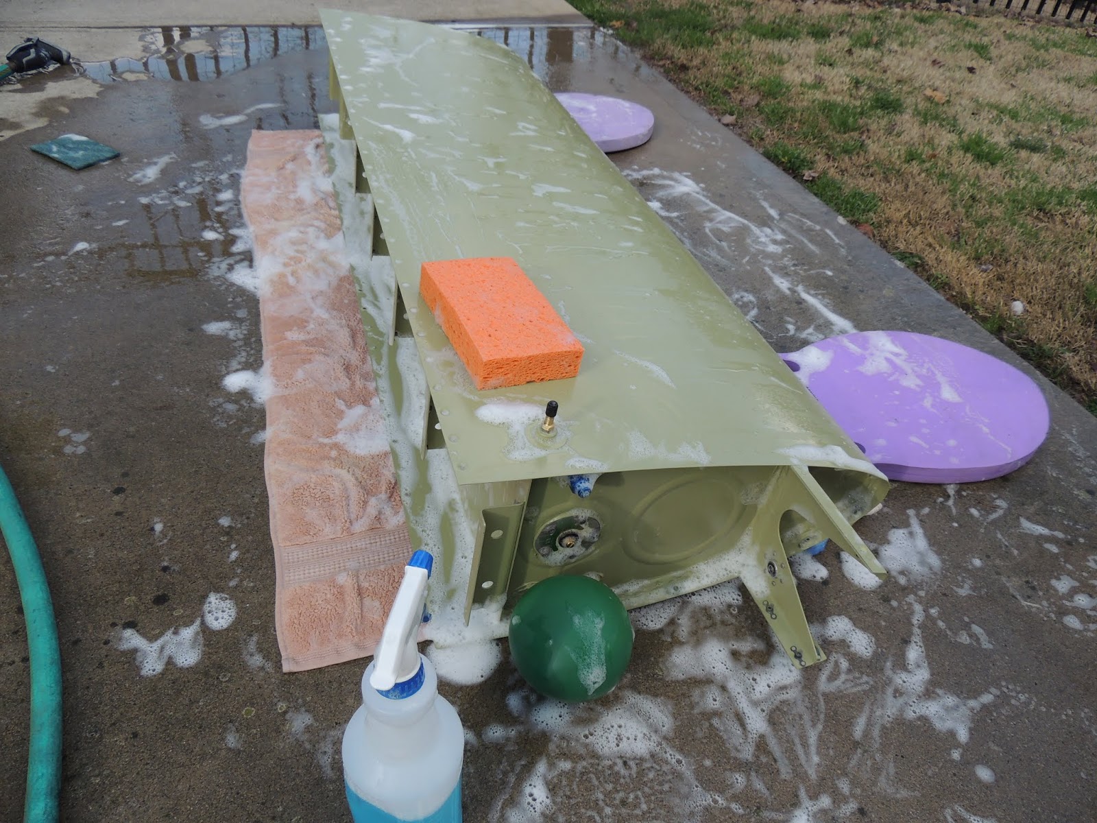
So, with that in mind, here's the process I used to prep and prime the tank skins. First, with tanks on the workbenches, I lightly sanded the skins with
220 grit 3M flexible sandpaper . I then did an initial cleaning using a small amount of naptha on a clean rag. Next, I moved the tanks outside and did my usual prime prep process. I used
PreKote and a maroon scotch-brite pad to further clean/scuff the skins,..rinsed with water, and then moved back inside where I used a blow dryer to dry the skins. After I was sure the skins were dry (a couple hours) I primed the tanks with the
Akzo Nobel primer.
Once primed,..and dried, I decided to do one final leak check (just so I can sleep better at night) of the tanks before installation.
 |
| Final leak check of the fuel tanks before installation. Once again, I used the pressure test method and soapy water (Dawn dishwashing liquid) to check for bubbles/leaks. |
 |
| I used the bubble mixture liberally on all surfaces to check for leaks. |
 |
The inflated ballon shown here is not really used to determine a leak free tank. The balloons primary purpose is to prevent over pressurizing the tank. It is interesting to watch the ballon size increase/decrease as temperature increases/decreases.
As a final "feel good" test, I did leave the balloons on the tanks overnight. The next morning both were still inflated. Good enough for me. Tanks are going on! |
With the tanks primed, final leak testing complete, I have no more excuses to delay installing the tanks on the wing assembly.
 |
| VERY carfully placing the left tank into position so that it can be secured to the wing structure. |
 |
| Installing the tank can easily be done solo. However, having an extra pair of hands..and eyes available is always a benefit. Neighbor Scott was available and was on-hand to help out. We had already installed/removed the tanks several times previously when checking fitment and skin gaps. We place pillows and towels on the floor to help support the tank while we maneuver into position. |
 |
| The tank fit is very nice, and actually "snaps" into position because of all the dimpled holes for the attachment screws. It will actually hold itself in place without any screws because of the dimples....although I still kept the support pillows, towels, and knees in position until a few screws were in place. |
 |
| Here Scott places the tank attachment screws along the bottom of the wing. We used a pair of these Double Drive Screwdrivers with new #2 phillips tips that worked out nicely. There are 77 screws that attach the tank to the spar and adjacent wing leading edge assembly. The screws are threaded into nutplates attached to the wing spar that were installed about a year ago! Time flies when your having fun:) |
 |
| There are 21 AN3 bolts that are inserted through pre-drilled holes in the spar that thread into nutplates attached to the Z-brackets on the baffle of the fuel tank. Here, I'm using a torque wrench to final tighten these bolts. |
 |
| Here's the AN3 bolts with torque-seal applied. Some of these won't be easily visible when the bottom skins are installed. However, I use the striping to let me know the fitting has been final torqued. Sometimes after a few days, and working on other stuff, it can be difficult to remember...at least for me. |
 |
| Bottom view of installed left fuel tank. |
 |
| Top view of installed right fuel tank. One quick note here for future builders. I didn't break the edges of the fuel tank skins because of skin thickness, large dimples, etc., and the fit turned out good. However, one thing that I probably could have done, and will do on right tank, is to slightly break the inboard/aft corner (only the corner) of the skin (top and bottom). The corner I'm talking about is just above fuel cap in picture above. Mine was OK without the break, but is very slight raised after tightening the corner screw. Don't think anyone but me will ever notice, but thought I'd mention as something to consider. |
 |
| Here's the right wing after tank installation. |